Table of Contents

Summary of Contents for Leantechnik lifgo
- Page 1 & lean SL 5.0 – 5.3 ® ® Mechanical arrest system Assembly instructions LEANTECHNIK AG Year of manufacture: 2012 / Datum: 17.12.2012 / Version: 00 CE coordinator: Lukas Piofczyk / Editor: Martin Siemann www.leantechnik.com...
- Page 2 Index Rules Introduction Machine designation Contact address Warranty Product responsibility Risk assessment Declaration of incorporation Scope of delivery Symbols used Product information Intended use Inappropriate use Technical data (data sheet) Dimension sheet Weights and dimensions Load capability Adjusting drive Safety instructions General information on component operation Choice of personnel and qualifications Transporting the mechanical arrest system...
-
Page 3: Function Description
Function description Operating process Installation positions 6.2.1 moves the lift load Gearbox Gear moves the lift load 6.2.2 rack Gearbox Unlocking Locking Required procedure Proximity switches Maintenance Screw connections Rust protection Lubrication Lubrication and maintenance points Spare parts Standard parts List of documents and drawings Troubleshooting and fault correction 11.1... -
Page 4: Machine Designation
This designation should be used in communications and any requests for information. In the re- mainder of this manual, the mechanical arrest system will be referred to as ‘ASS’, ‘component’ or ‘system’. LEANTECHNIK AG is the manufacturer of the mechanical arrest system. 1.3 Contact address LEANTECHNIK AG... -
Page 5: Warranty
1.5 Product responsibility LEANTECHNIK AG, as manufacturer of the component, and the operator are responsible for the component and the individual components it comprises. The responsibility of the operator relates primarily to operating safety and maintenance of the component. - Page 6 We declare herewith that the partly completed machine designated below complies with the EU Machinery Directive 2004/42/EC and subsequent amendments through to its interfaces: Mechanical arrest system (ASS) for Designation / type: lifgo , lifgo linear, lean SL ® ® ®...
-
Page 7: Scope Of Delivery
1.8 Scope of delivery The LEANTECHNIK AG scope of delivery comprises the following items: · Mechanical arrest system · Pneumatic system · Proximity cylinder · Assembly drawing · Operating instructions in English · Assembly and acceptance at LEANTECHNIK AG The scope of delivery does not include: ·... -
Page 8: Product Information
It may only be used to protect systems / machines / equipment against falling or sudden collapse during inspections or in the event of repair work. The mechanical arrest system may only be used together with lifgo , lifgo linear or lean SL ®... -
Page 9: Dimension Sheet
3 Technical data (data sheet) 3.1 Dimension sheet Schmierbohrung für Lifgo und lean SL Ritzel/Zahnstange Passbohrung Für Zahnstangeschut Steckanschluss für Luftschlauch Näherungsschalter Gewicht - lifgo Gewicht - lifgo linear Gewicht - lean SL... -
Page 10: Weights And Dimensions
3.2 Weights and dimensions Mechanical arrest system Unit (ASS) for lifgo ® 124,5 164,5 216,5 197,5 124,5 164,5 216,5 Ø 8,2 through Ø 10,2 through Ø 13 through ⨆ ⨆ ⨆ ↧ ↧ ↧ Ø12 Ø14 10,6 Ø20 12,6 45,5 68,5 ↧... -
Page 11: Safety Instructions
· All changes at the component that deviate from the original layout must be recorded in these instructions. · If any malfunction occurs then the cause must be eliminated immediately. If the cause of the malfunction cannot be identified and/or eliminated, then help must be obtained immediately from a specialist or from the company LEANTECHNIK AG. - Page 12 · The use of spare parts not supplied by LEANTECHNIK AG invalidates the component warranty since we do not accept any liability for such spare parts.
- Page 13 The minimum legal age of personnel must be observed. 4.3 Transporting the mechanical arrest system The mechanical arrest system is transported in its assembled state. = > see the documentation for lifgo , lifgo linear and lean SL ®...
- Page 14 4.4 Storing the mechanical arrest system The component is treated with a preserving agent ex-works. The parts are therefore protected against for a maximum of 6 months if stored in a dry environment. The corrosion protection at all unpainted areas (sliding areas, gear racks) must be inspected be- fore admission into storage and renewed if necessary.
-
Page 15: Maintenance And Repair
4.7 Maintenance and repair Caution! The safety notes in section 4 apply! The mechanical arrest system must not be repaired. If damage occurs, the complete mechanical arrest system must be replaced! The mechanical arrest system must be installed and removed by specialist personnel. Maintenance must be performed under the best possible conditions. -
Page 16: Other Provisions
· The safety instructions and provisions set out in the maintenance manuals for the individual machines such as the lifgo , lifgo linear and lean SL must also be observed! ®... -
Page 17: Transport And Lifting Instructions
5 Transport and lifting instructions 5.1 General The mechanical arrest system must be lifted and moved by hand. = > see the documentation for lifgo , lifgo linear and lean SL ® ® ® If lifting cables or slings are used then it is important to make sure that these do not touch the proximity switches and hoses on the cylinder since this could deform or destroy parts and the component may then be unable to perform its function. -
Page 18: Operating Process
ASS can also be used as a ® ® positioning unit for a given value. Please consult us for further information! The secured force is 5 times greater than the nominal force of the associated lifgo or lean SL ® ®... - Page 19 6.2 Installation positions 6.2.1 Gearbox moves the lift load 6.2.2 Gear rack moves the lift load...
-
Page 20: Proximity Switches
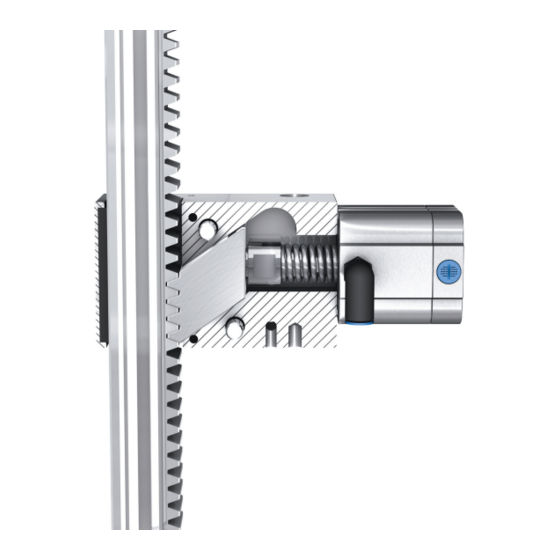
6.3 Gearbox = > see the documentation for lifgo , lifgo linear and lean SL ® ® ® The dimensions at the contact points with the gearbox can be found in the assembly drawings. 6.4 Unlocking The attached air cylinder disengages a release bar from the gear rack and is held in this position as long as pressure is still present in the cylinder. -
Page 21: Maintenance
7 Maintenance 7.1 Screw connections = > see the documentation for lifgo , lifgo linear and lean SL ® ® ® 7.2 Rust protection To ensure their antifriction properties, the smooth metal surfaces of the ASS have film of oil or grease. -
Page 22: Spare Parts
There are no spare parts for the mechanical arrest system. Defective mechanical arrest systems must be replaced in their entirety. The manufacturer’s ordering address can be found in section 1.3. 9 Standard parts LEANTECHNIK AG’s suppliers are listed below: Name Supplier Electrical components... -
Page 23: Troubleshooting And Fault Correction
11 Troubleshooting and fault correction 11.1 General This section contains troubleshooting information. It is intended to simplify the task of identifying the sources of faults. But, here again, the general rule applies: If the source of a fault cannot be unambiguously identi- fied then, if in doubt, contact the manufacturer of the component.