Table of Contents
Advertisement
Quick Links
Specifications
Power Supply
24VAC/DC ( +/- 8.3%)
Power Consumption
< 2VA
(2) Independent Single Pole, Double Throw mechanical
Output
Relays
Contact Rating
1A @ 120VAC, 2A @ 30VDC
Response Time
40 - 120ms
Hysteresis
4% of setpoint
2-35 Amps (ACS035)
Setpoint Ranges
25-400 Amps (ACS400)
Setpoint Adjust
Two 3/4-turn potentiometers
1.1x range continuous
Sensed Current
3x range for 6 seconds
Limit
5x range for 1 second
Isolation Voltage
UL508, UL tested to 1240VAC
Frequency Range
40-65 Hz
Sensing Aperture
1.31 in (33.3 mm) dia.
-Temp -4 to 122°F (-20 to 50°C)
-Humidity 0-95% RH, Non-condensing
Environmental
-Pollution degree 2
-Altitude 2000 meters
Case
UL 94V-0 Flammability rated thermoplastic
cULus listed E222847
Certifications
CE
For products intended for the EU market, the
following is applicable to the CE compliance of
the product:
The ACS035/ACS400 Series may comply with EN 61010-1
CAT III 300V max line-to-neutral measurement category. If
insulated cable is used for the primary circuit, the voltage rating
of the measurement category can be improved according to
the characteristics given by the cable manufacturer.
Use 24V input power and fuse at 5 amps. Power source
overvoltage category I as defined per EN 61010-1.
Part Number Key
A C S 035 - 2C - 24 - F
CASE STYLE
F - Fixed Core
POWER SUPPLY
24 - 24 VAC/DC
OUTPUT
2C - (2) SPDT relay outputs,
independant setpoints
RANGE
035 - 2-35 Amps AC
400 - 25-400 Amps AC
SENSOR TYPE
ACS AC current operated switch
Warning! Risk of hazardous voltage
When operating the device, certain parts may
carry hazardous live voltage (e.g., primary
conductor, secondary terminals). The device
should not be put into service if the installation is
not complete.
Warning! Risk of electric shock or
personal injury
Safe operation can only be guaranteed if the
device is used for the purpose for which it was
designed and within the limits of the technical
specifications. When this symbol is used, it
means you should consult all documentation to
understand the nature of potential hazards and
the action required to avoid them.
AutomationDirect.com (ADC)
3505 Hutchinson Road, Cumming, GA 30040
Phone: (800) 633-0405 or (770) 889-2858
ACTS - Inst - Rev 1
0820
P-N 394000024
ACS035/ACS400
SERIES
INSTRUCTIONS
Quick Start Guide
1. Route monitored wire through aperture.
2. Mount the sensor to a DIN rail or panel.
3. Connect power supply and output wiring.
a. Use 30-12 AWG copper wire and tighten termi-
nals to 7 in-lbs torque.
b. Ensure supply power and load matches that
shown on sensor label.
4.
Adjust setpoints.
a. Use trip adjust potentiometers to select
setpoints.
b. LED shows Green with power supply
connected, Amber when the current has
exceeded the setpoint.
®
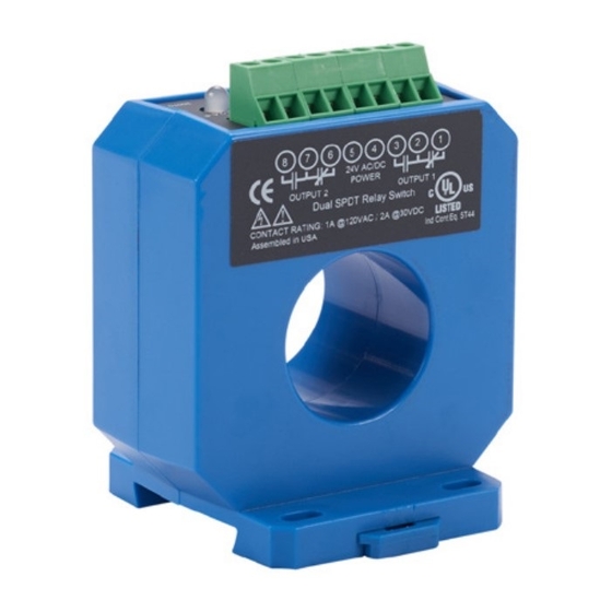
Part No. ACS035-2C-24-F
Advertisement
Table of Contents

Subscribe to Our Youtube Channel
Summary of Contents for AutomationDirect AcuAMP ACS035 Series
- Page 1 Use 24V input power and fuse at 5 amps. Power source overvoltage category I as defined per EN 61010-1. AutomationDirect.com (ADC) 3505 Hutchinson Road, Cumming, GA 30040 Phone: (800) 633-0405 or (770) 889-2858 ACTS - Inst - Rev 1...
- Page 2 Description Setpoint Adjustment Troubleshooting continuted: B. Monitored current is below minimum required. The ACS035 and ACS400 Series products are powered, Loop the monitored wire several times through the aperture The ACS035 and ACS400 Series setpoints are adjusted current-operated switches which trigger when sensed until the “sensed”...
Need help?
Do you have a question about the AcuAMP ACS035 Series and is the answer not in the manual?
Questions and answers