
Summary of Contents for S2Tech NCTE 7000 Series
- Page 1 Instruction manual and data sheet Torque Sensor Series 7000 Version 20/01 – State December 2020 via Imperia 28 - 20142 Milano www.s2tech.it email: info@s2tech.it...
- Page 2 NCTE AG® Torque Sensor Series 7000 Instruction Manual and Data Sheet. This instruction manual is property of NCTE AG®, D-82041 Oberhaching Unauthorized duplication, even in part, is not permitted. State: December 2020 via Imperia 28 - 20142 Milano www.s2tech.it email: info@s2tech.it...
-
Page 3: Table Of Contents
Starting up ............................8 Operation during regular mode......................8 Irregular operation, actions in case of failures .................. 8 Safety instructions ..........................8 Service, maintenance and repair ....................... 8 3.10 Disposal.............................. 8 via Imperia 28 - 20142 Milano www.s2tech.it email: info@s2tech.it... - Page 4 Additional profile sleeve for NCTE flange sensors (accessory) ..............14 Wiring diagram ............................16 10 Sensor wiring ............................16 11 Speed sensor ............................17 12 Speed Sensor ............................17 13 Order options ............................18 14 Accessories .............................. 19 via Imperia 28 - 20142 Milano www.s2tech.it email: info@s2tech.it...
-
Page 5: Instruction Manual
The torque sensor system consists of a calibrated sensor, signal acquisition / -processing integrated in the housing, a 5 m long connection cable with plug (Binder plug no. 99-5630-15-12). Enclosed you will find the corresponding calibration certificate and the warning notes. _______________________________________________________________________________________ Page 5 of 20 via Imperia 28 - 20142 Milano www.s2tech.it email: info@s2tech.it... -
Page 6: Safety
2.5 Transport and handling During handling, storage and transport, make sure that the sensor is not exposed to strong magnetic or electromagnetic fields (e.g. degaussing coils). _______________________________________________________________________________________ Page 6 of 20 via Imperia 28 - 20142 Milano www.s2tech.it email: info@s2tech.it... -
Page 7: Torque Sensor Series 7000
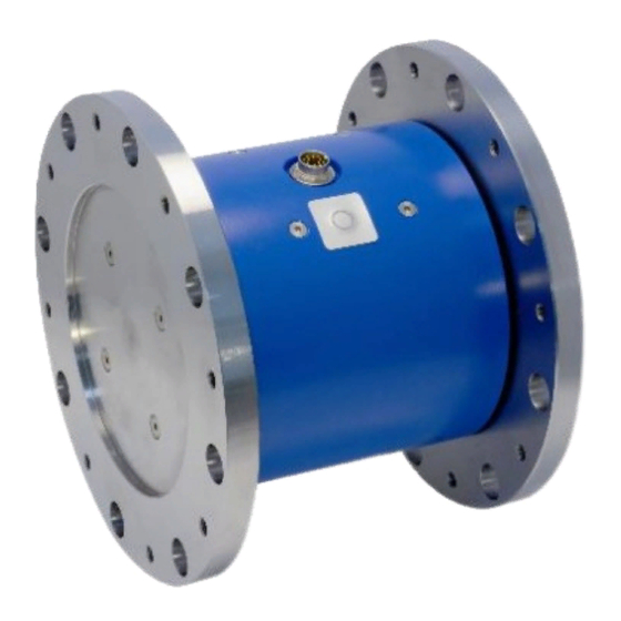
Electrical interface: A flange socket for power supply and signal output is attached to the top of the housing. (Pin assignment see Chapter “9 Wiring diagram") _______________________________________________________________________________________ Page 7 of 20 via Imperia 28 - 20142 Milano www.s2tech.it email: info@s2tech.it... -
Page 8: Starting Up
Repairs and recalibrations can only be carried out by NCTE AG personnel. 3.10 Disposal The device must be returned to NCTE AG, Raiffeisenallee 3, D-82041 Oberhaching for disposal. _______________________________________________________________________________________ Page 8 of 20 via Imperia 28 - 20142 Milano www.s2tech.it email: info@s2tech.it... -
Page 9: Data Sheet
Note: In case of overload, the sensor leads to a measurement offset. In such case, the sensor needs to be recalibrated at NCTE AG. The sensor should be operated only within the specified nominal torque range. _______________________________________________________________________________________ Page 9 of 20 via Imperia 28 - 20142 Milano www.s2tech.it email: info@s2tech.it... -
Page 10: Load Characteristics
% ME: Related to the measuring range. Zero point can be set to 5 V using a tare button. The exact sensor-specific values can be found in the calibration certificate supplied. _______________________________________________________________________________________ Page 10 of 20 via Imperia 28 - 20142 Milano www.s2tech.it email: info@s2tech.it... -
Page 11: Emv Emission Data
Based on the non-contact measurement principle the torque sensor is quite insensitive to bending and shearing forces. Self-aligning couplings are recommended in case of dynamic loads. _______________________________________________________________________________________ Page 11 of 20 via Imperia 28 - 20142 Milano www.s2tech.it email: info@s2tech.it... -
Page 12: Dimensions
_______________________________________________________________________________________ Dimensions Additional profile shafts for NCTE flange sensors (accessories) Profile shaft 6 teeth (1 3/4''), ≤ 4500 Nm continuous dynamic load _______________________________________________________________________________________ Page 12 of 20 via Imperia 28 - 20142 Milano www.s2tech.it email: info@s2tech.it... - Page 13 _______________________________________________________________________________________ Profile shaft 6 teeth (1 3/8''), ≤ 2500 Nm continuous dynamic load Profile shaft 20 teeth (1 3/4''), ≤ 5000 Nm continuous dynamic load _______________________________________________________________________________________ Page 13 of 20 via Imperia 28 - 20142 Milano www.s2tech.it email: info@s2tech.it...
-
Page 14: Additional Profile Sleeve For Ncte Flange Sensors (Accessory)
Profile shaft 21 teeth (1 3/8''), ≤ 3000 Nm continuous dynamic load Additional profile sleeve for NCTE flange sensors (accessory) Profile sleeve 6 teeth (1 3/4'') ≤ 5000 Nm continuous dynamic load _______________________________________________________________________________________ Page 14 of 20 via Imperia 28 - 20142 Milano www.s2tech.it email: info@s2tech.it... - Page 15 _______________________________________________________________________________________ Profile sleeve 6 teeth (1 3/8''), ≤ 5000 Nm continuous dynamic load Profile sleeve 20 teeth (1 3/4''), ≤ 5000 Nm continuous dynamic load _______________________________________________________________________________________ Page 15 of 20 via Imperia 28 - 20142 Milano www.s2tech.it email: info@s2tech.it...
-
Page 16: Wiring Diagram
Supply voltage GND Connector Supply voltage V 9 … 28 V Power supply and Black USB GND outputs Purple Grey-Pink +5 V Red-Blue 10 Sensor wiring _______________________________________________________________________________________ Page 16 of 20 via Imperia 28 - 20142 Milano www.s2tech.it email: info@s2tech.it... -
Page 17: Speed Sensor
Magnetic (Hall effect) speed sensor with 1 CPR or 60 CPR. Parameter Min. Typ. Max. Unit Operating frequency 8000 Analogue signal bandwidth Upper level Output signal Lower level Output signal _______________________________________________________________________________________ Page 17 of 20 via Imperia 28 - 20142 Milano www.s2tech.it email: info@s2tech.it... -
Page 18: Order Options
We would be pleased to provide you with further information about serial products in a personal contact under Phone: +49 (0)89 66 56 19 30 or by e-mail: sales@ncte.de. _______________________________________________________________________________________ Page 18 of 20 via Imperia 28 - 20142 Milano www.s2tech.it email: info@s2tech.it... -
Page 19: Accessories
You can obtain further or additional accessories and special requests in a personal discussion with your contact person for series products by calling +49 (0)89 66 56 19 30 or by e-mail: sales@ncte.de. _______________________________________________________________________________________ Page 19 of 20 via Imperia 28 - 20142 Milano www.s2tech.it email: info@s2tech.it... - Page 20 Your experts for magnetostrictive sensors via Imperia 28 - 20142 Milano www.s2tech.it email: info@s2tech.it...
Need help?
Do you have a question about the NCTE 7000 Series and is the answer not in the manual?
Questions and answers