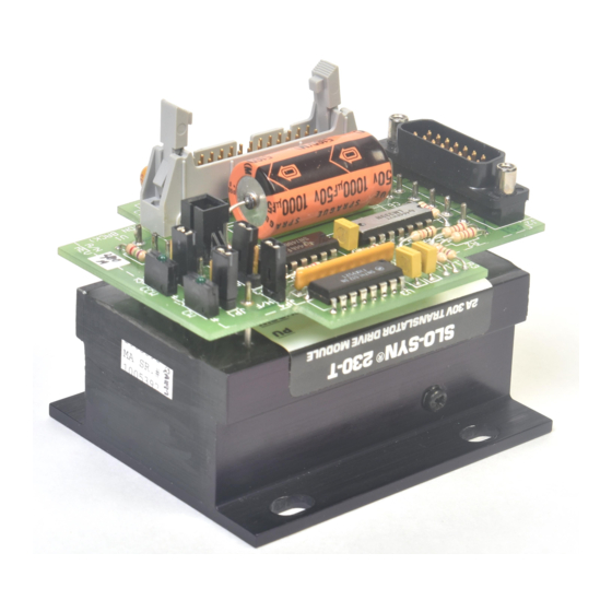
Superior Electric SLO-SYN MICRO Series Instructions Manual
Translator oscillator modules types 230-toh and 430-toh
Hide thumbs
Also See for SLO-SYN MICRO Series:
- Instructions manual (57 pages) ,
- Installation instructions manual (26 pages)
Summary of Contents for Superior Electric SLO-SYN MICRO Series
- Page 1 (217) 352-9330 | Click HERE Find the Danaher Motion / Superior Electric 430-EPI at our website:...
- Page 2 Instructions SLO-SYN MICRO SERIES ® Translator Oscillator Modules Types 230-TOH and 430-TOH Artisan Technology Group - Quality Instrumentation ... Guaranteed | (888) 88-SOURCE | www.artisantg.com...
-
Page 3: Express Start-Up Procedure
The Power Supply peak ripple voltages must not go higher than 32 volts or lower than 26 volts. POWER CONNECTOR (mates with J2 on printed circuit board) Superior Electric part number B209270-003 AMP part number 640599-5 MOTOR CONNECTOR (mates with J4 on printed circuit board) Superior Electric part number B215744-007 Electrovert part number 25.600.0753... - Page 4 RECOMMENDED POWER SUPPLY CONFIGURATIONS RECOMMENDED POWER SUPPLY CONFIGURATIONS SINGLE UNIT APPLICATIONS MULTIPLE UNITS FROM ONE POWER SUPPLY FIGURE 1 FIGURE 2 II. DRIVE 1. Make sure the motor to be used is compatible with the drive. Refer to the Section 3.3 for a list of compatible motors. 2.
- Page 5 1. Check the quality of the ac line voltage using an oscilloscope IV. Wiring Practices - “Dos and Don’ts” and a line monitor, such as Superior Electric’s VMS series. If line voltage problems exist, use appropriate line conditioning, such Do the following when installing or wiring your drive or indexer: as line filters or isolation transformers.
- Page 6 Recommended Wiring Practices SEE NOTE 2 SEE NOTE 1 NOTES: Recommended Cable Types Superior Electric cable part numbers: 215851-007 5 feet (1.5 meters) long 215851-008 10 feet (3 meters) long Superior Electric cable part numbers: 215801, 216066-001, 216067-001, - SEE NOTE 3 216022-001, etc.
- Page 7 1. Clockwise and counterclockwise directions are properly ori- ented when viewing the motor from the lable end. • Superior Electric disclaims any liability for operating this unit with- out the correct filter capacitor. 2. Motor connector, J4, consists of 7 pins arranged symetrically •...
-
Page 8: Motor Connections
Figure 2.1 shows the mounting hole loca- Motor and I/O Signal Pin Connections tions and diameters. It is recommended that 6-32 or 8-32 screws be It is suggested that a Superior Electric motor cable be used. They used for mounting. are available as follows:... -
Page 9: Section 3: Specifications
The 230-TOH and 430-TOH can be used with 4-lead, 6-lead and 8- Accel/Decel adjustable range: lead SLO-SYN motors. Figure 2.2 shows the correct connections for each possible motor configuration. 50ms to 2 sec. Oscillator stability: Velocity; Accel/Decel ± 5% over temperature and power supply range. -
Page 10: Electrical Specifications
3.5.2 OUTPUT TO MOTOR 3.4 MECHANICAL SPECIFICATIONS 3.5.2.1 Motor Connections Size (inches/mm): 3.7”D x 6.3”W x 2.25”H (94mm D x 160mm W x 57mm H) Assignment: J4: 7 pins on oscillator board (See Figure 2.2) Weight (lbs/kg): 230-TOH: 1.5 (0.68 kg) Assignment 430-TOH: 2.0 (0.91 kg) Vom —... -
Page 11: Environmental Requirements
The functions that the module performs are: • Adjustable acceleration and deceleration NOTE: The bar denotes low logic, active state • Adjustable base speed Wire Size: 28 AWG minimum • Clockwise/counterclockwise direction control Run Length: 50 feet (15 meters) max.; 15 feet (4.6 meters) max. •... -
Page 12: Section 6: Operating Instructions
5.2 CW/CCW (DIRECTION) - Pin 2 5.10 PULSE OUT - Pin 10 A logical high causes the motor shaft to step in the clockwise di- Produces a pulse (square wave output) from oscillator. Connect rection as viewed from the label end of the motor. A logical low, or to “PULSE IN”... - Page 13 Connect HI SPEED POT 1 to HI SPEED POT 2 by placing posi- 2. Connect RUN (J1, pin #6) to SIGNAL COMMON. tion 3 of switch S1 in the “on” (closed) position when no external 3. Turn “Base Speed Pot” (R4) clockwise to increase base speed. control is required.
- Page 14 5. Adjust Deceleration potentiometer (R1). Clockwise movement Measure acceleration with an oscilloscope connected be- tween HI SPEED POT 1 and SIGNAL COMMON. Oscilloscope increases deceleration time. should be triggered when RUN (J1 pin #6) goes low. 6. Repeat steps 2 - 5 until desired deceleration is reached. The following table give approximate settings for the Deceleration Then make the following settings: Potentiometer (R1).
- Page 15 TYPICAL SPEED VS. TORQUE CHARACTERISTICS 230 SERIES MOTION CONTROLS Artisan Technology Group - Quality Instrumentation ... Guaranteed | (888) 88-SOURCE | www.artisantg.com...
- Page 16 Artisan Technology Group - Quality Instrumentation ... Guaranteed | (888) 88-SOURCE | www.artisantg.com...
- Page 17 TYPICAL SPEED VS. TORQUE CHARACTERISTICS 430 SERIES MOTION CONTROLS Artisan Technology Group - Quality Instrumentation ... Guaranteed | (888) 88-SOURCE | www.artisantg.com...
- Page 18 Artisan Technology Group - Quality Instrumentation ... Guaranteed | (888) 88-SOURCE | www.artisantg.com...
- Page 19 430 SERIES MOTION CONTROLS (Continued) Artisan Technology Group - Quality Instrumentation ... Guaranteed | (888) 88-SOURCE | www.artisantg.com...
-
Page 20: Section 8: Troubleshooting
If a malfunction occurs that cannot be corrected by making these In General: correction, contact Superior Electric. • Check all installation wiring carefully for wiring errors or poor con- nections. SECTION 9: COMPONENT LAYOUT •... - Page 21 Superior Electric's factory or a warehouse of Superior Electric in the event that the equipment is purchased from Superior Electric or for a period of two years from the date of shipment from the business establishment of an authorized distributor of Superior Electric in the event that the equipment is purchased from an authorized distributor.


Need help?
Do you have a question about the SLO-SYN MICRO Series and is the answer not in the manual?
Questions and answers