Advertisement
Installation, Operation & Maintenance Manual
0518
3300 Fern Valley Road, Louisville, Kentucky 40213 USA
502.969.8000 phone 502.969.5911 fax info@topworx.com
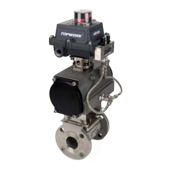
DXP with 4-20mA Position Transmitter
The DXP combines position sensors, internal mount pilot device and an
on-board spool valve into a single enclosure.
• Explosion-proof Class I, Div.1, Groups C & D (Ex d IIB+H2, II 2 G)
GO Switch, Mechanical, Proximity and Inductive Sensor switch
•
options
• Optional Solenoid Pilot Valve
Table of Contents
2
3
Installation
4
Calibration & Operation
6
7
www.topworx.com
Advertisement
Table of Contents

Summary of Contents for Topworx DXP
- Page 1 Installation, Operation & Maintenance Manual DXP with 4-20mA Position Transmitter The DXP combines position sensors, internal mount pilot device and an on-board spool valve into a single enclosure. • Explosion-proof Class I, Div.1, Groups C & D (Ex d IIB+H2, II 2 G) GO Switch, Mechanical, Proximity and Inductive Sensor switch •...
- Page 2 DXP 4-20mA Installation, Operation & Maintenance 502.969.8000 Features and Specifications 4-20mA Position Monitorinig Description 4-20mA Position Monitorinig Description 4-20mA Position Monitorinig Description 4-20mA Position Monitorinig Description 4-20mA Position Monitorinig Description The 2-wire 4-20mA transmitter will generate a nominal 4 – 20mA output for full-range actuation of the valve. The transmitter is capable of generating signals below 4mA and above 20mA if the position sensor indicates an out of range value.
- Page 3 4-20mA Position Transmitter Module and Stand Alone Potentiometer Typically the 4-20mA Position Transmitter module and potentiometer options are already installed in TopWorx valve controller products. Use the following installation directions only if you are replacing or upgrading an existing unit:...
- Page 4 (As shown in Illustration 6) The module is now ready for calibration/operation Before mounting the DXP to an actuator, make sure the potentiometer alignment marks are aligned as shown in Illustration 4 with the valve in the closed position.
- Page 5 The complete calibration process including error paths is shown in the Figure 1. The software can detect several errors during calibration (See Table 1). TRANSMITTER BOARD ASSY POTENTIOMETER CALIBRATION BUTTON 1 2 3 4 5 6 7 8 9 10 11 12...
- Page 6 DXP 4-20mA Installation, Operation & Maintenance 502.969.8000 Figure 1 Calibra Figure 1 Calibra tion Flow Chart tion Flow Chart Figure 1 Calibra Figure 1 Calibra Figure 1 Calibration Flow Chart tion Flow Chart tion Flow Chart...
- Page 7 Warranty TopWorx warrants that each item of new equipment manufactured by it will be free from defects in material and workmanship under normal use and service; its obligation under this Warranty, being limited to making good, at its factory, and part of parts thereof, which shall be returned to it with transportation charges prepaid, within one year after the date of the purchase of such equipment by the original purchaser, and which its examination shall disclose to its satisfaction to have been thus defective.
- Page 8 About TopWorx TopWorx is the leader in field networking, valve control, and position sensing solutions for the process industries. Our products and services help plants, mills, and pipelines improve their performance by making it easy to implement modern automation technologies.
Need help?
Do you have a question about the DXP and is the answer not in the manual?
Questions and answers