Advertisement
Quick Links
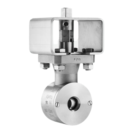
IOM Ramén Ball Sector Valve type KS DN 25
Ramén Ball Sector Valve type KS DN 25
Table of contents
Safety instructions............................................................................................................2
Valve material codes.........................................................................................................3
Pressure and temperature limits .......................................................................................................... 4
Installation ........................................................................................................................................ 5
Maintenance ..................................................................................................................................... 7
Ramén Valves AB l Fredsforsstigen 22 A, SE-168 67 BROMMA, Sweden
Office: +46 8 598 931 00 l E-mail: info@ramenvalves.com | www.ramenvalves.com
1
Advertisement

Summary of Contents for Ramen Valves KS Series
-
Page 1: Table Of Contents
IOM Ramén Ball Sector Valve type KS DN 25 Ramén Ball Sector Valve type KS DN 25 Table of contents Safety instructions…………………………………………………………………………………...…………2 Valve material codes……………………………………………………………………………………………3 Pressure and temperature limits ......................4 Installation ............................5 Maintenance ............................. 7 Ramén Valves AB l Fredsforsstigen 22 A, SE-168 67 BROMMA, Sweden Office: +46 8 598 931 00 l E-mail: info@ramenvalves.com | www.ramenvalves.com... -
Page 2: Safety Instructions
Safety instructions WARNING! Risk for serious injury when valve with actuator is bench tested. Avoid handling the valve with hands or fingers inside the valve! Be very careful when handling a valve which has been in abrasive service. Worn valve can have sharp edges on ball sector and seat. -
Page 3: Valve Material Codes
Storing Valve shall be stored in a clean and dry area preventing corrosion and fouling. It shall be operated to fully open position. Protection plates shall not be removed until the valve shall be mounted. Valve material and execution codes The valve body has an execution code stamped in per following table. -
Page 4: Pressure And Temperature Limits
Pressure and temperature limits Temperature related max working pressure in bar for material EN 1.4460: +100 +150 +200 +250 PN10 PN16 14,5 13,5 11,5 PN25 21,5 20,5 17,5 PN40 Temperature limits for seat- and sealing material O-ring seals (Type KS) Seat ring EPDM Material... -
Page 5: Installation
Installation Valve actuator The valve is normally equipped with an actuator. Depending on the application it can be a hand lever or a remotely controlled pneumatic or electric actuator. The actuator may have limit switches (on-off application) or positioner (continuous control). Installation This product shall only be inspected, installed and used by a person who has relevant training or experience. - Page 6 IMPORTANT! Install the valve in such position that injury on person, or damage on property, is avoided in case of leakage from sealing or flange joints. Also, make sure that, in case of leakage, inflammable media do not come in contact with electrical components or hot surfaces which can cause fire or damage on property.
-
Page 7: Maintenance
Startup The valve shall be operated and controlled that closing- and opening functions are correct before start- up. Check that the valve operates within its max- and min-positions. Limit-switches, positioner, feed- back signal and torque switches shall be checked for correct function. Start-up shall be done gradually and under careful attention. - Page 8 Disassembly DN 25 (1") a) Loosen and remove screws (11) and inlet cover ring (2). b) Lift out seat ring (10) carefully from its groove using a pointed tool. and the O-rings (15 and 16). Loosen the nut (12) and pull out fastening flange (1A). d) Push bearing sleeve (4) into the valve and remove split ring (4A).
- Page 9 Reassembly Proceed in reverse order. O-rings (13, 14 15 and 16) shall be lubricated with suitable grease before reassembling. Please note ”Important when assembling ” below. If the o-rings show sign of wear or other damage, check if the most appropriate o-ring material has been used. Check the sliding ring (13A) replace if necessary.
- Page 10 After reassembly Pressure test the valve with air from the valves outlet side and with the valve closed. The valve immersed in water or with leakage spray shall be bubble tight over shaft seals and seat. I small bubbles can be detected around the shafts it can be enough to actuate the valve a few times allowing the O-rings to find its correct position.
- Page 11 Tool for mounting shaft and drive shaft Rulon bearing (9) Sliding ring (13A) O-ring (13) Ramén Valves AB l Fredsforsstigen 22 A, SE-168 67 BROMMA, Sweden Office: +46 8 598 931 00 l E-mail: info@ramenvalves.com | www.ramenvalves.com...
Need help?
Do you have a question about the KS Series and is the answer not in the manual?
Questions and answers