Advertisement
Quick Links
TO THE PROFESSIONAL OR INSTALLER:
Instructions must remain with installation.
GENERAL EASY FLUSH SYSTEM
INSTALLATION
Please read these instructions carefully.
Note before you proceed with the
installation of this product that the
manufacturer's guideline has to be
respected. Failure to comply to instructions
and designed operation of this product,
may void the warranty.
Your product has been carefully packaged
at the factory to prevent damage during
shipping. However, occasional damage
may occur due to rough handling. Carefully
inspect your product for damages that could
cause failures. Report any damage to your
carrier or your point of purchase.
INITIAL START UP PROCEDURES:
1- Inspect the pump and the sewage tank for
any obvious condition that may necessitates
cleaning, correction, adjustement or repair.
2- Assure that the pump is secure and vertical
for proper operation.
3- Assure that there is adequate clearance
from any combustible materials or structure.
Stored materials must be kept away from
the pump.
4- Assure that the motor is securely plugged
into a proper 'GFCI' electrical outlet.
5- Test the 'GFCI' outlet by pressing its test
switch. This should prove that the outlet
is energized and will trip off to protect
against a ground fault. Be sure to reset
the 'GFCI' by pressing its reset switch.
(Repeat this step monthly)
6- Lift the float to assure that the pump will
start when required. (Step 7 below will test
submersible pumps with enclosed floats).
7- Pour pails of water in the sewage tank to
turn the pump on. Assure that any check
valve present will permit the sewage to flow.
2013 TURBO Printed in Canada TI026
8- Observe that the plumbing can pump
the sewage safely out of the residence.
(Repeat this step monthly)
SAFETY INTRUCTIONS:
Before installation and operation, follow these
procedures:
A- Check with your local electrical and
plumbing codes to ensure you comply with
the regulations. These codes have been
designed with your safety in mind. Be sure
you comply with them.
B- A separate circuit must be lead from the
home electrical distribution panel properly
protected with a fuse or a circuit breaker. We
also required that a ground fault circuit be
used as well as a 'GFCI' receptacle. Consult a
licensed electrician for all wiring.
C- The ground terminal on the three prong
plugs should never be removed. They are
supplied and designed for your protection.
D- Never make adjustments to any electrical
appliance or product with the power
connected. Do not only unscrew the fuse
or trip the breaker, remove the power plug
from the receptacle.
IMPORTANT
ELECTRICAL CONNECTION:
For pumping systems using more than one
pump, each pump needs to be connected to a
separate dedicated circuit protected by a fuse
or breaker. This way, the power supply of one
pump will not stop operating if the fuse of one
of the pumps burns or if the breaker of one of
the pumps trips.
IMPORTANT NOTICE:
The following are minimum requirements in
order to protect your residence from flooding.
It is a small investment but it is your personal
responsibility to protect your home, family and
valuables. Failure to comply with the following
requirements will also void your warranty:
- An Alarm system model T50454 has to be
installed to advise you of any malfunctions.
Pump selection, proper and adequate
installation are a must to comply with local
by-laws and need to be adhered to.
1
Advertisement

Subscribe to Our Youtube Channel
Related Manuals for Turbo T40040


Summary of Contents for Turbo T40040
- Page 1 7- Pour pails of water in the sewage tank to turn the pump on. Assure that any check valve present will permit the sewage to flow. 2013 TURBO Printed in Canada TI026...
-
Page 2: Installation Steps
INSTALLATION STEPS: PHOTO A We recommend that you install your system in a clean location where there is adequate room Flange screws (4) for servicing at a later date. Protection from freezing temperatures and good ventilation should be considered as well, to provide the Toilet brass screws (2) system an environment for long life. - Page 3 STEP 7 STEP 11 Install the pump in the "EASY FLUSH" unit, Cut a short piece of foam seal (3 3/4") as the aligning the pump legs with the moulded basic wire slots seal, then glue it to fit the sloats’ shape.
- Page 4 1 800.361.1820. These type of switch are NOTE: The system is sold with two (2) possible exclusive to TURBO. types of switch. Follow the instructions for the type supplied with your unit. Mechanical...
- Page 5 STEP 19 STEP 22 " " Install your toilet in the desired location with OPTION To install an additional shower or sink a wax ring and bolts. Slide the brass screws in unit to the "Easy Flush" System, use the the proper slot position.
- Page 6 EASY FLUSH APPLICATION: STEP 1 Position your "Easy Flush" System as per instructions. STEP 16 Install the 2" check valve in STEP 2 a vertical position. Install the unit between 2" X 6" floor joist. STEP 15 STEP 3 Install a 2" "Aqua Flex" Purchase required rubber gasket under the plumbing parts.
-
Page 7: Repair Parts
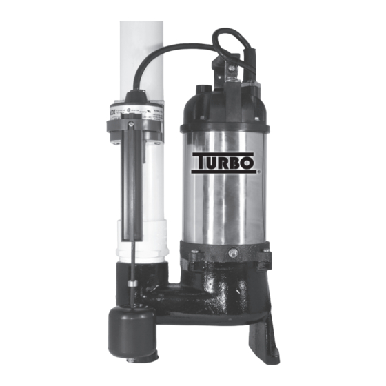
Replacement pump YEAR WARRANTY MODEL T40040 1/2HP Discharge: 2" NPT Electric cables: 4900 GPH 19' piggyback type Head of 25’ (7.5m) • Water cooled • Cast iron and stainless steel construction • 2" solid handling capabilities • Vortex impeller, clog-free type, made of cast iron •... - Page 8 2" X 3' discharge pipe with adaptor 450504 3" "Aqua Flex" gasket 450502-O Rubber gasket under flange 450445R Easy Flush top lid T40040 Sewage pump 450444R Easy Flush tank unit 450503 2" "Aqua Flex" gasket (2) 450502 Cast iron flange...
- Page 9 TYPICAL HIDDEN SOLUTION: Designed to be installed between 2" X 6", it’s easy to built a complete bathroom with the "Easy Flush" System. Compare to a traditional sewage system, the only different component is the tank, which is designed to receive the toilet cabinet.
- Page 10 STEP 1 STEP 5 The photo 1 shows you how to begin your The next step consists in covering the tank. project by installing the 2" X 6". No nail or A 3/8" plywood on all floor area except for the screw should perforate the tank.
- Page 11 PHOTO 9 STEP 9 At this step, it is the time to screw the gypsum board on the 2" X 4" and finish the installation of the toilet cabinet by fixing same to the flange (Photos 14 and 15). PHOTO 14 PHOTO 10 PHOTO 15 STEP 7...
- Page 12 NOTES:...
Need help?
Do you have a question about the T40040 and is the answer not in the manual?
Questions and answers