Advertisement
Quick Links
Max 100m from the power supply, using twisted cable Ø 0.5
Max 200m from the power supply, using twisted cable Ø 0.8
17-0102-EN
+
- D+ D-
Alert
Right next to the 12-0110-EN
NEVER PLACE THE 17-0102-EN MODULE IN A METAL CASE!
: Alert and door opening are not possible at the same time without adding another 12-0110-EN card.
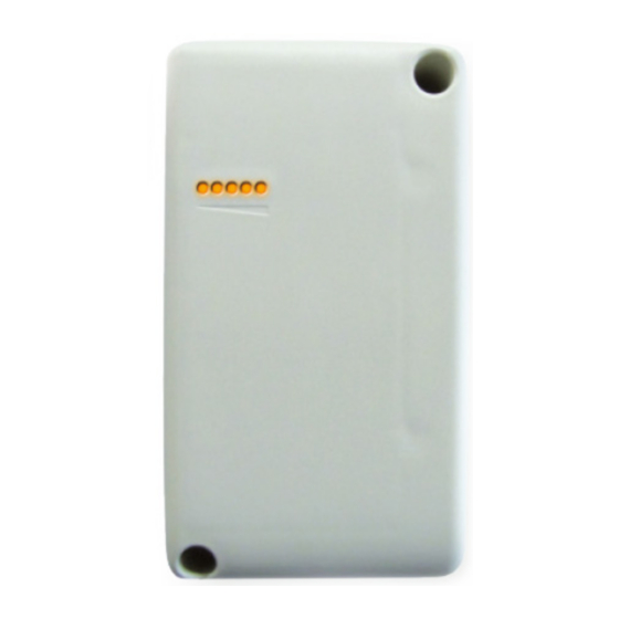
The LEDs on the 17-0102-EN module indicate the surrounding GPRS network reception quality: the more LEDs you have lit, the better
your reception.
The presence of keypad beeps indicates that the central unit is correctly connected ( D+/D- bus wired).
The presence of back lighting indicates that the keypad is correctly powered.
DO NOT FORGET TO
You will need this to set up your equipment at www.intratone.com
Page 1 / 2
Wiring
12-0110-EN
12/24 V DC - 2 A
MP
(NOT SUPPLIED)
For optimal functioning, ensure that you have three LEDs lit.
NOTE THE 17-0102-EN CONTRACT NO. AND THE RELATED ENTRANCE.
06-0131-EN: Installation guide
W
IRING DIAGRAM
+ - D+ D-
PB
-
C R T
Door Relay
Pushbutton
04-0106-EN
+
- D+ D-
EN-V231-0121-AA
Advertisement

Related Manuals for Intratone 04-0106-EN

Summary of Contents for Intratone 04-0106-EN
- Page 1 The presence of back lighting indicates that the keypad is correctly powered. DO NOT FORGET TO NOTE THE 17-0102-EN CONTRACT NO. AND THE RELATED ENTRANCE. You will need this to set up your equipment at www.intratone.com 06-0131-EN: Installation guide Page 1 / 2...
- Page 2 3. The varistor supplied is 12 V. IF YOU INSTALL SEVERAL POWER SUPPLIES, ENSURE THAT YOU CONNECT EACH EARTH (-) TOGETHER. The complete pack for managing an isolated door with 1 square proximity reader (04-0106-EN) 1 relay central unit (12-0110-EN) 1 module (17-0102-EN)
Need help?
Do you have a question about the 04-0106-EN and is the answer not in the manual?
Questions and answers