Advertisement
Quick Links
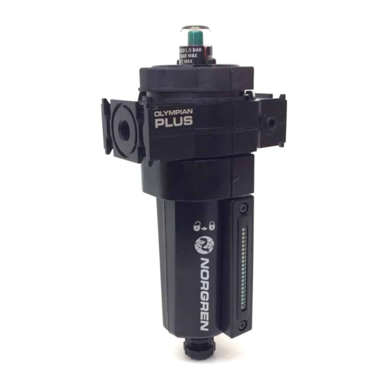
Option selector
Bowl/
Element
C
Standard
H
High flow
Port
2
1/4"
3
3/8"
4
1/2"
6
3/4
Technical features
Fluid: Compressed air
Maximum pressure:
Guarded transparent bowl: 10 bar (150 psig)
Metal bowl: 17 bar (250 psig)
Operating temperature*:
Transparent bowl: –20° ... +50°C (0° ... +125°F)
Metal bowl: –20° ... +65°C (0° ... +150°F)
* Air supply must be dry enough to avoid ice
formation at temperatures below +2°C (+35°F).
Particle removal: Down to 0,01 µm
Air quality: Within ISO 8573-1, Class 1.7.2
Maximum remaining oil content in outlet air:
0,01 mg/m
at +21°C (+70°F)
3
with an inlet concentration of 17 ppm
Maximum flow at 6,3 bar (90 psig) inlet
pressure**: 16 dm
/s (34 scfm) F64C, 28 dm
3
(60 scfm) F64H
** to maintain stated oil removal performance.
Automatic drain connection: 1/8"
Automatic drain operating conditions:
Minimum pressure: 0,7 bar (10 psig). Drain
openswhen bowl pressure drops below 0,2 bar
(3 psig)
Minimum air flow:
1 dm
/s (2 scfm) required to close drain
3
Nominal bowl size: 0,2 litre (7 fluid oz)
Materials:
Body: Zinc
Bowl:
Metal: Aluminium
Transparent, optional: Polycarbonate
Metal bowl liquid level indicator lens, standard:
Grilamid
Metal bowl sight glass, optional: Pyrex
Element: Composite materials
Elastomers: Synthetic rubber
Mechanical service indicator materials:
Body: Transparent Nylon
Internal parts: Acetal
Spring: Stainless steel
Elastomers: NBR
Replacement Items
Service kit,
contains required items circled: 4380-200
Prismatic sight glass
4380-040
Pyrex sight glass
4380-041
Filter element:
F64C
4344-01
F64H
4344-02
Manual drain
684-84
Automatic drain
3000-97
Mechanical service Indicator (1) 5797-50
Installation
1.Install unit vertically in air line -
• vertically (bowl down),
• with air flow in direction of arrow on body,
• upstream of regulators, lubricators, and
cyclingvalves,
F64˙ – ˙˙˙ – ˙˙˙
Servive life indicator
D
Mechanical service indicator
N
Without indicator
Thread
A
PTF (1/8 PTF gauge ports)
B
ISO Rc taper (1/8 ISO Rc gauge ports)
G
ISO G parallel (1/8 ISO Rc gauge ports)
N
No thread (basic unit)
• as close as possible to the air supply when
used asa main line filter,
• as close as possible to the device being
serviced when used as a final filter.
2. Before assembling the basic unit into the yoke
the port seal o-rings should be lightly smeared
with o-ring grease.
3. Locate clamp ring under lugs on top of yoke,
offerbasic unit into yoke with directional
arrows correctly aligned (an interference fit
prevents assembly if misaligned) before
engaging and fullytightening the clamp ring.
4. Turn bowl or bowl guard fully clockwise into
body before pressurizing. Lock symbols on
body andbowl guards must align.
/s
5. Auto-drain units may be fitted with a short
3
drain pipe and connector, minimum 5 mm
bore, to theG1⁄8 bottom outlet.
6. Push bowl, or bowl with guard, into body and
turnfully clockwise before pressurizing.
7. Install a Norgren general purpose filter with a
5 µm element upstream of the oil removal filter
to obtainmaximum element service life.
8. Turn bowl into body until arrowhead on bowl
is aligned with or to the right of the arrowhead
on the body.
A
Servicing
1. Open manual drain to expel accumulated
liquids.Keep liquids below element (58, 60).
2. To operate automatic drain manually, lift
operatingpin in bottom outlet with a blunt rod.
3. Replace filter element when pressure drop
acrosselement exceeds 0,7 bar (10 psig). The
mechanicalservice indicator shows
approximately full red.
Diassembly
1. Shut off inlet pressure. Reduce pressure in
inletand outlet lines to zero.
2. For ease of maintenance the unit can be
removedfrom the yoke by unscrewing the
clamp ring, whichwill jack the unit out down
wards.
3. Lift and turn the filter bowl counterclockwise
and remove with bowl o-ring.
4. Disassemble in general accordance with the
item numbers on exploded view. Do not
remove thedrains or the service indicator
unless replacementis necessary. Remove and
replace only if theymalfunction.
Our policy is one of continued research and development. We therefore reserve the right to amend,
without notice, the specifications given in this document. (1999 - I&M8075e) © 2015 IMI International s.r.o.
Installation & Maintenance Instructions
Drain
A
Automatic
M
Manual
Q
Manual 1/4 turn
16
7
61
60
B
C
18
19
21
20
32
33
35
34
F64C, F64H Filter
Element
0
Coalescing
Bowl
D
Metal
P
Transparent with guard
R
Metal with Pyrex sight glass
6
8
1
59
58
26
22
25
28
24
27
23
40
47
36
39
46
42
38
41
37
I&M/en 8.240.10501
2
4
3
5
31
30
29
48
45
44
43
7/15
Advertisement

Related Manuals for IMI NORGREN F64C

Summary of Contents for IMI NORGREN F64C
- Page 1 Maximum flow at 6,3 bar (90 psig) inlet body andbowl guards must align. pressure**: 16 dm /s (34 scfm) F64C, 28 dm 5. Auto-drain units may be fitted with a short (60 scfm) F64H drain pipe and connector, minimum 5 mm ** to maintain stated oil removal performance.
- Page 2 F64C, F64H Filter Installation & Maintenance Instructions Cleaning 1. Element (58, 60) cannot be cleaned. Clean plastic bowl and lens (45) with warm water only. Cleanindicator (1) with dry, clean cloth. Clean otherparts with warm water and soap. 2. Rinse and dry parts. Blow out internal passages in body (6) with clean, dry com pressed air.