Table of Contents
Advertisement
Quick Links
Advertisement
Table of Contents

Related Manuals for BK Precision 1801

Summary of Contents for BK Precision 1801
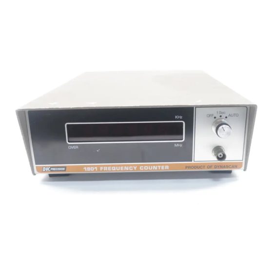
- Page 1 mazmr1801 6-DIGIT, AUTORANGING FREQUENCY COUNTER...
- Page 2 TEST INSTRUM ENT SAFETY Normal use of this instrument exposes you to a certain amount of dan ger from electrical shock because measurements must sometimes be taken in equipment that contains high voltage. An electrical shock causing 10 milliamps of current to pass through the heart will stop most human heart beats.
- Page 3 INSTRUCTION MANUAL B & K - PRECISION MODEL 1801 6 - DIGIT, AUTORANGING FREQUENCY COUNTER 64 70 West Cortland Street Chicago, Illinois 60635...
-
Page 4: Table Of Contents
TABLE OF CONTENTS Page INTRODUCTION ..........4 SPECIFICATIONS ..........4 OPERA TING PROCEDURE A. Controls and Features ......�....7 B. Interpretation of Display Readings ....... 7 C. -
Page 5: Introduction
INTRODUCTION The B & K Model 1801 is a high-quality, lightweight, diodes) for units and overrange indication. autoranging counter designed for freguency measurement An internal time base of 10 MHz is generated by a in the range from 20 Hz to 40 MHz. A front panel function crystal-controlled oscillator. - Page 7 3 4 567891 3 4 567891 3 4 � 67891 3 4 567891 3 4 5 6 7891 I I 11111 I I I I 11111 I I I I 11111 Showino ouaranteed and typical sensitivity vs. frequency , 1-�--·-+---+-- ----i--+-, , , , , ---1----�--.
-
Page 8: Operating Procedure
OPERATING PROCEDURE A . CON TRO LS AND FEA TUR E S 1. FUNC TION SWITCH. Turns instrument on and frequency in kHz. This indicator is always on when selects preset (I SEC.) or AUTO counting range. In the function switch is in the SEC position, and the the AUTO range mode, proper gate interval is auto... - Page 9 frequency 1,654,321 Hz would then appear as shown in Fig. 6. Note that the unused digits register as zeros and the dedmal point is retained the kiloHerl!. position. Fig. 9. The reading is displayed as 000.321 kHz. which is . . . a<.:tually 321 Hz.
-
Page 11: Applications
matches, the importance of minimizing the voltage 4. In the "1 SEC" range, the display shows the reading to the counter becomes obvious. to Hertz (least significant digit, LSD), even though the most significant digits (MSD) may be beyond the A convenient method of paralleling the load and display reading ( overrange indicator flashes). -
Page 12: Modifications
3. Square Wave or Pulse Train Measurement 2. Internal time base output: If it is desired to use the internal time base of the 1801 for other purposes, In some cases, miscounts can occur when measuring such as a secondary frequency reference, the unit can the frequency of squa�e waves or a pulse train,... -
Page 13: Theory Of Operation
THEORY OF OPERATION S. AUTO-RANGING CIRCUIT The Model 1801 Frequency Counter consists of an input This part of the circuit consists of an underrange section, time base and control circuit, counter section, detector, overrange detector, binary counter and de display, auto-ranging circuit, and power supply. -
Page 14: Block Diagram
r.---- ------ - -- - -- ----- -------- --, LEVEL ,- ----, SIGNAL .._ _ _,. THRESHOLD 1---M TRANSLATOR WIDE BAND 1------1.a O .R. INPUT & DETECTOR AMPLIFIER CONDITIONER (J) COUNTERI CONTROL GATE SECTION .. _____ _. '---..----' .. _____ _, --- - ----'11 ___ -- _...,___, '-------J... -
Page 15: Timing Diagram
""' TEST REMARKS FUNCTIONS WAVE FORMS POINTS GENERAL: (1) ALL CONTROL SIGNAL S Ac'TIVA TE AT LOGIC CLOCK 1 OR 2 "l" LEVELi (2) ALL SIGNAL S (1<1JO OR 3 --TIME BASE 10 mS E C ARE AT TTL LEVELS. (3) .100 Hz PERIOD+ 2 5 0 mSEC �... -
Page 16: Appendix
APPENDIX DETERMINATION OF APPROXIMATE DAMPING RESISTOR ---, r------ -, I� 3 ft. ___ ,,. I Counter I 1�1 ---=-_J L __ _ '...J Fig. A-1. Use of damping resistor in frequency measurements. Fig. A-2. Equivalent circuit of counter input. where C i 20 pF ( typical) Because of cable capacitance C c and the counter's input capacitance C i a voltage divider is formed after a series... -
Page 17: Warranty Instructions
TEST INSTRUMENT SAFETY (continued from inside front cover) Some equipment with a two-wire ac power cord, including some with a polarized power plug, is the "hot chassis" type. This includes most recent television receivers and audio equipment. A plastic or wooden cabinet insulates the chassis to protect the customer. - Page 18 � SW18 '---=-- - - ------.. :L+l t?'�--=-�;:===l==t=<� , , _________ _ _ _j / r --- -------------- -- MODEL 1801 DIGITAL FREQUENCY COUNTER 488-145 -9-00 IC · · n :. --- ----- --- ------ - __ J r ------ - - - _______ _ __ r �...
Need help?
Do you have a question about the 1801 and is the answer not in the manual?
Questions and answers