Table of Contents

Subscribe to Our Youtube Channel
Summary of Contents for DesignTech DC-24
- Page 1 MIDI Driver Boards Models DC-24 and DC-48 Instructions for Installation and Configuration Version 2.0 June 2017 DesignTech Systems, Inc. PO Box 828 Downers Grove, IL Telephone 630-324-8199 Fax 866-896-4431 www.dtsmidisystems.com Email info@flighttech.com...
-
Page 2: Table Of Contents
5. MIDI connections The information in this user guide may be subject to change without notice. No part of this document may be transferred or reproduced, digitally or otherwise, without prior consent from DesignTech Systems, Inc. Copyright © 2017 Osney Consulting Ltd. All rights reserved. -
Page 3: Introduction
Outputs can be either continuous, for driving indicator lamps, or pulsed for driving Stop Action Magnets (SAMs). DC-24 can drive up to 24 indicators, or 12 SAMs. DC-48 can drive up to 48 indicators, or 24 SAMs. DC-24 is available in two versions, one for lamp mode and the other for magnet mode. -
Page 4: Connections
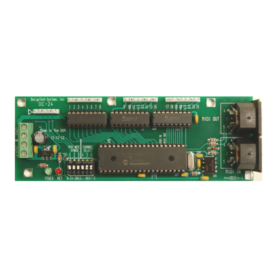
2. Connections DC-24 Outputs Outputs Outputs 9-16 17-24 MIDI Power connectors MIDI DIP switches Power Activity DC-48 Outputs Outputs Outputs Outputs Outputs Outputs 9-16 17-24 25-32 33-40 41-48 Power connectors Power LED DIP switches Activity LED MIDI MIDI... - Page 5 Power in: An 8v to 15v DC supply should be connected to the screw terminals provided, with the positive line to the right. MIDI in: A standard MIDI-compliant input. MIDI “note on” and “note off” messages which match the channel and note range settings on the DIP switches will cause the outputs to be energized.
-
Page 6: Dip Switches
3. DIP switches DC-24 DC-48 Note MIDI Note MIDI range channel range channel Mode select Note range switches The settings for the note range switches are shown below: DC-24 Switch Note range (lamp mode) Note range (magnet mode) 0 - 23... - Page 7 48 - 95 24 - 47 96 - 127 48 - 71 72 - 95 96 - 120 MIDI channel switches DC-24 can operate on MIDI channels 9 to 16. DC-48 can operate on any MIDI channel. DC-24 Switch MIDI channel...
-
Page 8: Output Wiring
4. Output wiring DC-24 and DC-48 are normally supplied to work with a “pull to ground” (a.k.a. “common positive”) configuration. This means that you connect one side of each lamp or magnet to positive (typically +12v) and the board energizes an output by connecting the other side to ground. -
Page 9: Midi Connections
We have no connection with either company. In theory, it is possible to “daisy-chain” any number of DC-24 and DC-48 cards together by connecting the MIDI out port of one to the MIDI in port of the next. However, for best performance, we recommend that no more than four decoder cards be connected together in this way.
Need help?
Do you have a question about the DC-24 and is the answer not in the manual?
Questions and answers