Table of Contents
Advertisement
Quick Links
Monica
AN24™
Reference
Operator
Manual
100-TF-006 Revision F
00843
©Copyright Monica Healthcare
Ltd 2007-2009. All rights are
reserved
worldwide.
Reproduction in whole or part is
strictly prohibited without prior
consent of the copyright holder.
US law restricts this device to
sale by, or on the order of, a
physician.
Advertisement
Table of Contents

Summary of Contents for Monica Healthcare AN24
- Page 1 Monica AN24™ Reference Operator Manual 100-TF-006 Revision F 00843 ©Copyright Monica Healthcare Ltd 2007-2009. All rights are reserved worldwide. Reproduction in whole or part is strictly prohibited without prior consent of the copyright holder. US law restricts this device to sale by, or on the order of, a physician.
- Page 2 On your monitor, this sign indicates that there is detailed information in this book, which you must read before proceeding with your task. Monica ™ and AN24™ are registered trademarks of Monica Healthcare Ltd. Other brand names and product names are trademarks or registered trademarks of their respective holders.
-
Page 3: Table Of Contents
Contents Section 1 - Unpacking the AN24™ ......................5 Section 2 - Product Description ......................7 General description ....................................7 Patient attachment ....................................7 Data processing ...................................... 7 Data viewing and storage ..................................7 Heart rate calculation ....................................7 Heart rate data accuracy ..................................8 Uterine Activity from EHG .................................. - Page 4 AN24™ will not recharge ..................................29 10.8 AN24™ will not connect via USB................................30 10.9 AN24™ will not connect via USB and will not recharge ......................... 30 10.10 AN24™ will not connect via Bluetooth® ..............................30 Section 11 - Returns Procedure ......................31 11.1...
-
Page 5: Section 1 - Unpacking The An24
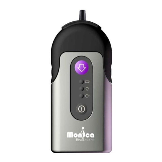
Section 1 - Unpacking the AN24™ Table 1 - The Monica AN24™ case should contain the following items Description 10 Monica AN24™ recorder/monitor [Item1, Figure 1] 11 Electrode lead connector [Item 2, Figure 1] 12 AN24™™ neck strap 13 Battery Charger and lead 14 AN24™™... - Page 6 2. Electrode leads connector 6. Battery status LED 5. Signal quality LED 4. Memory status LED 8. Event button 3. On/Off 7. Connector locks & release buttons 9. Neck Strap connection 1. AN24 body Figure 1 Monica AN24™ Controls and Indicators...
-
Page 7: Section 2 - Product Description
16 hours. 2.2 Patient attachment The Monica AN24™ is attached via a detachable lead assembly that in turn attaches to 5 disposable ECG electrodes placed on the abdomen of a pregnant woman to generate 3 signal channels. -
Page 8: Heart Rate Data Accuracy
ECG complex. In the event that the AN24™ is not confident of the accuracy of either the FHR or MHR, they will not be made available; the AN24™ will not ‘fill in’ any data. This method of providing a 2-second average is very different to the complex autocorrelation and rule-based methods used to calculate the FHR on Doppler based recorders. -
Page 9: Section 3 - Installation
A. Connect the lead on the supplied battery charger into the socket inside the top of the AN24™ body (1). Plug the battery charger into a mains outlet and switch on the mains outlet. The amber battery status LED (6) will flash until the device is charged, when it will be constantly lit. -
Page 10: Section 4 - Operating The An24
(Retrospective mode). Connection to a PC is required to set the time for the first recording. The AN24™ already running in Mode 1 can be set up to run in Mode 2 by making a wireless Bluetooth® connection using the Monica VR software (see 4.5 Wireless configuration). - Page 11 Attach the electrode leads connector (2) to the electrodes (16) following the colour code guide in Appendix B. Ensure that the electrode leads connector (2) is securely attached to the AN24™ (1), by pushing the two sections firmly together such that the two buttons (7) are engaged.
- Page 12 4.1.8 Secure the AN24™ If the patient wishes to carry the AN24™ it can either be held in their clothing (e.g. a pocket) or carried around the neck using the supplied neck strap (12). If the patient wishes to use the neck strap, attach it to the AN24™...
-
Page 13: During Monitoring
(3) followed by the event button (8) followed by the event button (8) again. This sequence of button presses must be completed within 4 seconds to turn the device off. When the AN24™ is switched off all three LED’s (4, 5 and 6) will flash three times. -
Page 14: Connecting To A Computer
C. Connect USB lead - Connect the AN24™-to-USB lead (14) into the socket inside the top of the AN24™ (1). Plug the USB end of the lead into a free USB port on the computer. The Monica AN24™ device will be automatically recognised by the computer and will provide status information. -
Page 15: Wireless Configuration
4.5 Wireless configuration If there is no data available for upload, the Monica VR program will provide the option to set-up a wireless real-time monitoring session and will ask you to identify the patient, by providing the patient’s name and hospital number. Monica VR will then take you through the set-up process. -
Page 16: Section 5 - Safety And Standards
5.1 General This section describes safety precautions that may appear within the manual and those that appear as symbols labels on the AN24™ itself. Furthermore, this section describes a group of precautions that are applicable, in general, when using the AN24™. -
Page 17: Intended Use
5.3 Intended use The Monica AN24™™ is a monitoring device for non-invasively measuring the • Fetal Heart Rate (FHR) • Maternal Heart Rate (MHR) • Uterine Activity (UA) • Maternal Movement (MMov) The Monica VR software, which accompanies the AN24™, enables the measured... -
Page 18: Standards
Monica Healthcare recommend that a repeat test is undertaken, using either the AN24™ or an alternative device to confirm the results from the initial test. The repeat test should be carried out in the case of either normal or abnormal results generated by the AN24™. 5.6 Safety WARNING: The Monica AN24™... - Page 19 (e.g. TENS machine, diathermy, impedance meter), then the AN24™ will not be able to detect the fetal heart rate. WARNING: Do not operate the Monica AN24™ if it fails to pass the power on self-test procedure, see Section 4.
- Page 20 Section 6 - Cleaning and Maintenance CAUTION: Do not immerse AN24™, connector or leads in liquid. When using solutions, use sterile/clean wipes to avoid pouring fluids directly on to the AN24™ and connector. Follow cleaning and disinfection instructions in Section 6 - Cleaning and Maintenance CAUTION: The water temperature must not exceed 40°C (104°F).
-
Page 21: Section 6 - Cleaning And Maintenance
Do not use aerosol preparations since they might contain organic solvents. Do not pour fluids directly on the unit and its accessories. Wipe the exterior of the AN24™ and leads three times. Prepare the detergent according to the manufacturer’s recommendations. If necessary scrub the AN24™, and leads with the solution using a soft bristled brush for five... -
Page 22: Batteries
AN24™ and leads have been cleaned following the same procedure described above. After the low level disinfections, wipe the AN24™ and leads three (3) times with sterile or distilled water to remove diluted bleach residue. Dry the AN24™, connector and leads thoroughly with a sterile soft towel or gauze surgical sponge. -
Page 23: Section 7 - Monica Accessories
100-PT-015 Soft silicon rubber protective boot (x5) 100-PT-004* Battery Charger (UK\ EU\ USA type) 100-PT-005* AN24™ – USB computer connection cable 100-PT-006* Monica VR installation CD (including user manuals & video) 100-PT-007* 3M red Dot 2236 skin prep tape sample... -
Page 24: Section 8 - Monica Vr Software
CTG trace. It is also provides the Monica AN24™ set-up tools to configure the unit and label and store the monitoring sessions for easy identification and retrieval. The functionality of the Monica VR software is explained in detail in the Monica VR Operating Manual, though the system requirements and installation instructions are described below. -
Page 25: Software Installation
8.3 Software Installation If a Monica VR Monitor (part no. 100-PT-040) was ordered with a Monica AN24™™ it will arrive with the VR software preinstalled and this section can be skipped A. Before beginning, please ensure the computer satisfies the system requirements. Please make sure the installer has administrative rights for the installation process and/or contact the network administrator. -
Page 26: Section 9 - Specifications
Section 9 - Specifications Measured Time Real-Time clock Maternal Movement 3 axis accelerometer Clinical Event Button Marker Abdominal 3 different channels Electrophysiological Signal Calculated Range 60-240 beats per minute 2 second average Range 40-240 beats per minute 2 second average Maternal Movement 4 levels –... -
Page 27: Section 10 - Troubleshooting
If green LED flickers, first check that the electrode lead connector cap is connected securely on both sides of the AN24™ (both buttons engaged). If this does not resolve the problem, put AN24™ into electrode check ‘Phase 1’ by pressing event button twice within a 2-second period The system will then ‘display’... - Page 28 If all the LED are on continuously (good connection), put the AN24™ into electrode check ‘Phase 2’ by pressing event button twice within a 2 second period. In ‘mode 2’ the electrode/skin impedance will be communicated to the user for the remaining two electrodes as follows: •...
-
Page 29: Signal Quality (Green) Led Constantly On
Memory Status (Orange) LED flashing This indicator will only light just after the AN24™ has been turned on and indicates that there is > 1 minute of data on the device. Upload / delete the data currently stored on the device (see Section 4 - ). -
Page 30: An24™ Will Not Connect Via Usb
Disconnect USB lead from both the AN24™ and computer. Reconnect USB lead and retry. If problem is not resolved, connect the AN24™ to the charger for half an hour and try connecting the recorder to the computer again. If the problem is not solved, contact Monica Healthcare for advice. -
Page 31: Section 11 - Returns Procedure
Section 11 - Returns Procedure 11.1 Maintenance There are no user serviceable parts in the Monica AN24™ or accessories. In the event of device failure or the battery needs to be changed, please contact Monica Healthcare or your local representative. -
Page 32: Appendix A - Ce Approvals
Appendix A - CE Approvals... -
Page 34: Appendix B - Electrode Placement
When the room where the patient is being monitored is filled with Drs, Midwives, Family, Children and other onlookers. In this situation it is advisable to leave the Monica AN24 in place and return when the patient situation has changed. Electrode Location It is important to correctly prepare the skin before the application of the electrodes. - Page 35 Midline Centre of the white electrode 3cm above the top edge of the navel Centre of the yellow electrode = 6cm Navel above the SP Symphysis pubis (SP) Gestation < 28 weeks Midline Fundus Centre of the white electrode 2cm below the fundus Centre of the yellow electrode = 6cm...
- Page 36 Midline Fundus Centre of the white electrode 5cm below the fundus Centre of the yellow electrode = 6cm above the SP Symphysis pubis (SP) Gestation > 33 weeks III. Preparation of the skin and electrode application It has been found that if the electrodes are placed directly onto the skin then an unacceptable skin-to- electrode resistance can occur.
- Page 37 Note: If unable to use a pen to mark the site an alternative MUST be used to mark the site. Example: patient’s fingers or ultrasound gel as markers. Take a section of prep tape and stick it to the end of your index finger. Using a brushing action firmly stroke the area between two opposing dots in one direction only to remove the dead skin and other debris away from the electrode site.
- Page 38 If the electrode skin impedance is not achieved for one or more of the electrodes as identified by the Monica AN24, QuickView or Monica VR, carefully peel back the problem electrode by holding the single strip of paper remaining so as not to touch the sticky part of the electrode as far as possible, so as to leave one edge in contact with the skin, and then rub the area with a 2% alcohol wipe before re-abrading applying firm pressure as described above.
-
Page 39: Lead Connection
Pull the top of the cover down and stretch the bottom of the cover over the base so it creates a tight fit around the AN24™. Connect the electrode leads connector to the AN24™... - Page 40 Monica Healthcare reserves the right to make changes in specification and/or discontinue any product or accessory at any time without notice or obligation and will not be liable for any consequences resulting from the use of this document. ® Bluetooth is a registered trade mark of Bluetooth SIG Inc.
Need help?
Do you have a question about the AN24 and is the answer not in the manual?
Questions and answers