Advertisement
Available languages
Available languages
Quick Links
Bedienungsanleitung
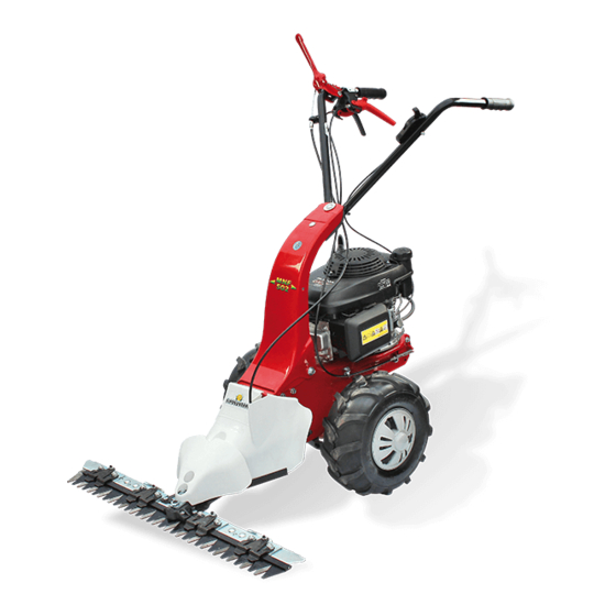
für M150RG Balkenmäher
Stand 01.06.2018
eurosystems Deutschland
Motorgeräte Handelsgesellschaft mbH
Im Fuchshau 14
D-73635 Rudersberg
Tel: +49 7183 / 30 590-0
Fax: +49 7183 / 30 590-20
info@eurosystems.info
www.eurosystems.info
Advertisement

Subscribe to Our Youtube Channel
Related Manuals for Eurosystems M150RG


Summary of Contents for Eurosystems M150RG
- Page 1 Bedienungsanleitung für M150RG Balkenmäher Stand 01.06.2018 eurosystems Deutschland Motorgeräte Handelsgesellschaft mbH Im Fuchshau 14 D-73635 Rudersberg Tel: +49 7183 / 30 590-0 Fax: +49 7183 / 30 590-20 info@eurosystems.info www.eurosystems.info...
- Page 8 6÷8 mm.
- Page 11 Costruttore Constructeur Manufacturer Hersteller Modello Modèle Type Modell Anno di costruzione Massa Année de construction Masse Year of construction Mass Baujahr Gewicht Numero di serie articolo – Progressivo Potenza in kW Numéro de série article - Progressif Puissance en kW Serial number - Progressive Power in kW Serienummer - Fortlaufend...
- Page 12 Innesto barra falciante Cutter bar clutching Embrayage barre Mähbalkenantrieb Innesto marcia avanti (Modello solo con Marcia avanti) Engage forward speed (Model with forward speed) Leggere il manuale prima di usare la Pericolo organi in movimento. Embrayage marche avant macchina. (Modèle avec marche avant) Danger ! Bodies in motion.
- Page 13 DATI TECNICI - TECHNICAL DETAILS - DONNEES TECHNIQUES - TECHNISCHE DATEN Modello solo con Marcia avanti - Model Modello con Retromarcia e marcia avanti with forward speed - Modèle avec marche - Model with reverse and forward gears - avant - Modell nur mit Vorwärtsgang Modèle avec marche arrière et marche avant - Modell mit Rück- und Vorwärtsgang Carreggiata - Path - Voie - Spurweite...
- Page 14 Istruzioni d’uso originali INTRODUZIONE Indice Gentile cliente, la ringraziamo per la fiducia accordata ai nostri prodotti e le auguriamo un piacevole utilizzo della sua macchina. Abbiamo creato queste istruzioni per l’uso allo scopo di assicurare, fin dall’inizio, un funzionamento privo di inconvenienti.
- Page 15 5 Non mettere in moto la macchina quando si è davanti alla barra, né avvicinarsi ad essa quando è in moto. Tirando la funicella di avviamento del motore, la barra e la macchina stessa devono rimanere ferme. 6 Assicurarsi sempre di avere buoni punti di appoggio durante la falciatura sui pendii. Non falciare in salita o discesa nel senso della pendenza, oppure su pendii con inclinazione superiore ai 10°.
- Page 16 Fig. 4A) indicata dalla freccia. Montare la fascia antivibrante (4) sotto il supporto manubrio (5) in corrispondenza dei due fori. Fissare il manubrio (6) tramite le viti (7), rondelle in gomma (8), rondelle (9 - 10) e dadi (11). Terminare il montaggio fissando la leva (2) al manubrio (6) tramite la vite (12). MONTAGGIO FILO ACCELERATORE CON MOTORE B&S 450 Series (Fig.
- Page 17 (3). Il cofano va fissato mediante la vite (1) nell’inserto filettato (5) dell’attacco barra. Attenzione: il filo comando barra (6) deve alloggiare nella sede (7) preposta. MONTAGGIO COFANO SPARTI ERBA (Fig. 12) Prelevare dall’imballo il cofano sparti erba (1) con già montati gli antivibranti (2). Il cofano va fissato mediante distanziali (3), rondelle (4) e viti (5) nei fori della piastra anteriore (6).
- Page 18 Fig. 20) Nel caso la retromarcia non funzionasse correttamente (scarso tensionamento della cinghia) occorre agire sul registro (2) installato sulla leva (1). Terminare serrando i dadi del registro. INNESTO E REGISTRAZIONE MOVIMENTO BARRA FALCIANTE (Fig. 17) Per innestare la barra falciante è sufficiente ruotare verso l’alto il fermo di sicurezza (2) e abbassare la leva (1).
- Page 19 proteggere barra e lama con sostanze anticorrosive ed antiossidanti. Lasciare raffreddare la motofalce prima di immagazzinarla, non riporla con la benzina nel serbatoio all’interno di un edificio, dove i vapori possono raggiungere una fiamma libera o una scintilla. Per ridurre il pericolo di incendio mantenere il motore, il silenziatore e il serbatoio della benzina liberi da foglie, erba, grasso ecc.
- Page 20 Translation of original user instructions Introduction List of contents Dear Customer: Thank you for your confidence in purchasing our products. We wish you to enjoy using our machines. The following working instructions have been issued to ensure you a safe and reliable use of the unit. Introduction If you carefully follow such information the machine will operate with complete satisfaction for long time.
- Page 21 5 Do not start the engine if anyone is standing in front of the cutter bar – the cutter and wheel drives must not be engaged. 6 Always mow across a slope. Never mow up or down a slope or on slopes with an inclination higher than 10°. 7 During operations you need to use ear protectors, sturdy footwear and long trousers should be worn.
- Page 22 ASSEMBLY OF THE THROTTLE WIRE WITH B&S ENGINE model B&S 450 Series (Fig. 5) Position the throttle drive lever (1) which is placed on the engine all its end ( stop position) following the arrow direction. Take the screw (2) and the corresponding terminal stop clamp away (4) using the suitable tubular spanner.
- Page 23 ASSEMBLY OF THE FIXED COVER (Fig. 11) remove the cover from its packaging (4) already fitted with the screw (1) the washer (2) and captive washer (3). The cover is secured by a screw (1) into the threaded insert (5) of the bar connection. Attention ! : the bar control cable (6) should be housed in the suitable seat (7) .
- Page 24 Fig. 20) In case the reverse speed is not properly working (because of the poor belt tensioning) you need to work on the adjuster gear (2) you can find on the lever (1). Finish the operations tightening the adjusting nuts. HOW TO CONNECT AND ADJUST THE CUTTING BAR (Fig.
- Page 25 free from leaves, grass or greasy substances. If the machine is not used for long periods it is essential to protect the blade and the bar using some anticorrosive and antioxidant materials. The presence of impurities or foreign bodies on the meadow, damages the teeth sharpening of the scything bar.
- Page 26 Traduction du mode d‘emploi original Introduction Index Cher client, nous vous remercions de la confiance que vous nous témoignez et vous souhaitons beaucoup de satisfaction dans son utilisation. Afin de garantir d’emblée un fonctionnement sans accrocs nous avons créé cette notice d’utilisation. Si vous Introduction observez exactement les indications suivantes votre appareil fonctionnera toujours à...
- Page 27 4) Vérifiez entièrement et avec soin le terrain à tondre. Éloignez tous objets à risque (pierres, bâtons, fils de fer, os, etc.). Ne tondez qu’à la lumière du jour ou en présence d’un bon éclairage. 5) Ne pas mettre en marche la machine lorsqu’on se trouve devant la barre et ne pas s’y approcher lorsqu’elle est en marche. Lorsqu’on tire sur la corde du lanceur, la barre de coupe et la machine ne doivent pas se mettre en marche (si c’était le cas, agir sur la vis de réglage du tendeur de courroie).
- Page 28 Montage mancheron et levier commande marche (Modèle seulement avec marche avant) (Fig. 4) Avant de fixer le mancheron au support, il faut introduire le fil (1 marche avant) déjà joint au levier (2) et au châssis de la machine dans le trou ouvert du mancheron Fig.
- Page 29 Montage capot fixe (Fig. 11) Enlever le capot (4) de son emballage avec la vis (1), rondelle (2) et rondelle (3) déjà montés. Le capot doit être fixe par la vis (1) dans la garniture filetée (5) de l’attelage de la barre. Attention : le fil de la commande de la barre (6) doit rester dans le bon logement (7).
- Page 30 Réglage et embrayage marche arrière (Fig. 19) Pour enclencher la marche arrière vous devez tourner en bas l’arrêt de sûreté (5) et Fig. 20) tirez le levier (4). Une fois le levier relâché (4) la machine s’arrête. si la marche arrière ne marche pas correctement (insuffisant tension de la courroie) il faut agir sur le registre (2) qui se trouve sur le levier (1).
- Page 31 la remiser et ne pas la mettre avec de l’essence dans le réservoir à l’intérieur d’un bâtiment, car les vapeurs peuvent atteindre une flamme libre ou une étincelle. Pour réduire le risque d’incendie, garder le moteur, le silencieux et la zone de stockage du carburant propre sans feuille, ni herbes ni même de graisse.
- Page 32 Übersetzung der originalen Betriebsanleitung EINLEITUNG Index Verehrter Kunde, wir bedanken uns für Ihr Vertrauen, das Sie in unsere Qualitätsprodukte setzen und wünschen Ihnen viel Freude beim Arbeiten mit Ihrem neuen Gerät. Um eine zuverlässige Inbetriebnahme von vornherein zu gewährleisten haben wir diese Betriebsanleitung geschaffen. Wenn Sie die folgenden Hinweise genau beachten, wird Ihr Gerät Einleitung stets zu Ihrer vollsten Zufriedenheit arbeiten und eine lange Lebensdauer besitzen.
- Page 33 Stöcke, Metalldrähte und Knochen vom Boden entfernen. Nur bei Tageslicht oder aber mit einer guten künstlichen Beleuchtung arbeiten. 5 Die Maschine nicht anlassen, wenn man sich vor dem Mähbalken befindet, und während des Betriebs Abstand vom Mähbalken halten. Wenn die Anlasserschnur gezogen wird, dürfen der Mähbalken und die Maschine sich nicht bewegen. 6 Immer sicherstellen, dass beim Mähen von Böschungen gute Auflagepunkte vorhanden sind.
- Page 34 Abb. 3A) Die Gummiabdeckung (4) unter die Halterung (5) auf der Höhe der zwei Löcher montieren. Der Handholm (6) mit Schrauben (7), Gummischeiben (8), Unterlegscheiben (9-10) und Muttern (11) befestigen. Der Hebel (3) am Handholm (6) mit den Schrauben (12) befestigen. Jetzt ist der Montage erledigt. MONTAGE HANDHOLM UND GANG BETÄTIGUNGSHEBEL (Modell nur mit Vorwärtsgang) (Abb.
- Page 35 MONTAGE MÄHANTRIEB AM GRUNDGERÄT Der Balkenmäher ist mit einer Kupplung ausgestattet, die die Verbindung des Mähbalkens am Grundgerät einfach und schnell erlaubt. Abb. 10) Bei ausgeschaltetem Motor und Maschine in waagerechter Stellung, wird den Zapfen (1) des Mähantriebes in den Sitz der Maschine (2) eingeführt. Den Keilriemen (3) an der Riemenscheibe (4) anbringen. Abb.
- Page 36 EINSTELLUNG DER LENKSTANGE (Abb.16) Die Höhe der Lenkstange kann im Verhältnis zur Körpergröße auf Hüfthöhe eingestellt werden. Die Schrauben (1 und 2) nicht vollständig lösen, die Höhe im Verhältnis zu den Langlöchern (3) einstellen und die Schrauben durch Anziehen blockieren. ANTRIEB UND EINSTELLUNG DES VORWÄRTSGANGES (Abb.
- Page 37 Ggf. Öl Typ SAE 80 nachfüllen. WICHTIG! Um eine Verunreinigung des Grundwassers zu vermeiden, darf Altöl nicht in Kanalisationssysteme bzw. Wasserläufe geschüttet werden. Altöllager befinden sich an allen Tankstellen oder an Mülldeponien, die über eine Zulassung laut Gemeindeverordnungen des Wohnsitzes verfügen. SCHMIERUNG DES MÄHBALKENANTRIEBES (Abb.
- Page 38 STÖRUNG Vor allen Wartungs- und Reinigungsarbeiten Zündkerzenstecker abziehen! Störung Beseitigung Motor springt nicht an Benzin auftanken. Gashebel auf Position “START” stellen. Zündkerzenstecker auf die Zündkerze aufstecken. Zündkerze überprüfen, eventuell erneuern. Kraftstoffhahn aufdrehen (nur für Motoren mit Kraftstoffhahn). Motorleistung lässt nach Luftfilter reinigen.
- Page 39 05/2016 cod. 322065115...
Need help?
Do you have a question about the M150RG and is the answer not in the manual?
Questions and answers