Advertisement
Quick Links
inSTrucTiOn ManuaL
Optronic SkyLine
™
Dobsonian Telescopes
#52908 8", #52910 10", #52912 12"
#52908
Copyright © 2014 Optronic Technologies
All Rights Reserved. No part of this product instruction or any of its contents may be reproduced,
copied, modified or adapted, without the prior written consent of Optronic Technologies.
IN 534 Rev. A 10/14
Advertisement

Summary of Contents for OPTRONIC SkyLine 52908
- Page 1 #52908 Copyright © 2014 Optronic Technologies All Rights Reserved. No part of this product instruction or any of its contents may be reproduced, copied, modified or adapted, without the prior written consent of Optronic Technologies. IN 534 Rev. A 10/14...
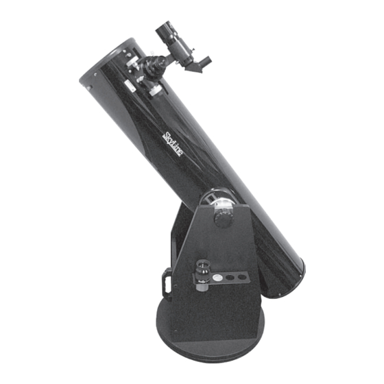
- Page 2 9mm 1.25" Finder eyepiece scope Dual-speed Crayford focuser Optical tube Altitude hub Side bearing Right side panel Altitude tension knob Left side panel Front panel 30mm 2" eyepiece Handle Eyepiece rack Dobsonian base Top groundplate Bottom groundplate Figure 1. The SkyLine Dobsonian (8" model shown)
-
Page 3: Table Of Contents
Read it over carefully shipping box and the optical tube assembly and accessories and if you still have questions, call Optronic Customer Service are contained in the second box. at 800-676-1343 or send an email to support@telescope.com. -
Page 4: Assembly
Optical tube assembly Side hub Dust cap Battery 30mm 8x50 RACI Side bearings Laser holder eyepiece, eyepiece, finder scope collimater 2" 1.25" Figure 3. The contents of the optical tube box. Not shown: 35mm extension adapter (2"). 2. assembly assembly of the Base The base needs to be assembled only once. - Page 5 Left Right side side panel panel Front panel Figure 6. a) Attach the two side panels to the front panel with the base assembly screws and included Allen wrench. b) The side panel with the two holes for the eyepiece rack should go on the left side.
- Page 6 Place the metal azimuth axle sleeve in the center hole of the bottom groundplate, as in Figure 10. Now place the azimuth bearing discs over the axle sleeve, with the black roller bearing disc sandwiched between the two gray discs (Figure 11). Pick up the top base assembly and place it on the bottom groundplate assembly, lining up the center hole in the top groundplate with the axle sleeve.
- Page 7 Flat surface Align top of faces up side bearings with “0” Figure 13. a) Remove the two screws in the side hub with the Allen wrench. b) Then align the side bearing with the slot in the hub and install with the screws, top screw first. c) Align the top of the side bearing with the “0” on the scale before tightening the screws.
-
Page 8: Using Your Telescope
3. using Your Telescope Moving the Telescope The Dobsonian design permits easy manual movement of the telescope in the altitude (up / down) and azimuth (left / right) directions (Figure 16). The azimuth motion should be smooth, with just enough resistance to keep the base from rotating when you want it to stop and stay put after you have slewed the telescope. - Page 9 Brass compression ring Thumbscrews 1.25" Adapter 2" Drawtube Accessory tension collar Fine focus thumbscrew knob Drawtube Coarse Coarse focus knob focus knob Drawtube lock thumbscrew Figure 17. a) The SkyLine’s 2" dual-speed Crayford focuser. b) Underside of the focuser. The other thumbscrew on the underside of the focuser is the Now look through the finder scope.
-
Page 10: Collimation
more light-collecting area, or aperture, can yield higher magnifi- cations than a smaller aperture telescope. The maximum practi- cal magnification for any telescope, regardless of optical design, is about 60x per inch of aperture. This translates to about 480x for the SkyLine 8". Keep in mind that as magnification is increased, the bright- ness of the object being viewed will decrease;... -
Page 11: Cooling The Optics
Mirror lock Collimation knobs (white) knobs (black) Cooling fan Secondary mirror collimation screws Power input jack Figure 19. a) The tilt of the secondary mirror is adjusted using the three Philips screws shown here. b) The primary mirror’s tilt is adjusted with the three black knobs on the rear cell. The three white lock knobs should be loosened a couple of turns first, and then lightly re-tightened once the adjustment has been made. -
Page 12: Specifications
This product is warranted against defects in materials or workmanship for a period of one year from the date of purchase. This warranty is for the benefit of the original retail purchaser only. During this warranty period Optronic Technologies will repair or replace, at Optronic’s option, any warranted instrument that proves to be defective, pro- vided it is returned postage paid.
Need help?
Do you have a question about the SkyLine 52908 and is the answer not in the manual?
Questions and answers