Table of Contents
Advertisement
Quick Links
Advertisement
Table of Contents

Subscribe to Our Youtube Channel
Summary of Contents for Royal Enfield C1
- Page 1 Controller & Driver User’s Guide...
-
Page 2: Table Of Contents
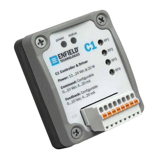
User’s Manual Page 1 of 12 Table of Contents Warnings & Notices ..............................2 Quick Start Procedure ............................3 Factory Default Setting ............................4 Position or Force Control ............................5 Pressure Control ..............................5 Flow Control ................................6 Wiring ..................................7 Potentiometers/Tuning ............................ -
Page 3: Warnings & Notices
While the product is low voltage, it contains open-frame electronic components and care should be taken to prevent un- intentional contact with the product to avoid damage to person or property. The C1 is an electro-static sensitive device. Use appropriate electro-static discharge (ESD) procedures during handling and installation. -
Page 4: Quick Start Procedure
User’s Manual Page 3 of 12 Quick Start Procedure 1. Configure Jumpers Configure the left side of Jumpers 2 and 3 to select a command input of 0…10Vdc or 4…20mA Configure the right side of Jumpers 2 and 3 to select a command input of 0…10Vdc or 4…20mA Configure Jumper 1 to select control algorithm 2. -
Page 5: Factory Default Setting
User’s Manual Page 4 of 12 Factory Default Setting Potentiometer Factory Default Condition Setting RP1 – Proportional Gain Fully Counter Clockwise Proportional gain is zero RP2 – Ramp Rate Fully Counter Clockwise Command is not being ramped RP3 – Minimum Feedback Fully Counter Clockwise No Adjustment to Minimum Position RP4 –... -
Page 6: Position Or Force Control
User’s Manual Page 5 of 12 Position or Force Control Pressure Control © 2012 Enfield Technologies WARNING: Installation and operation of electronic and high pressure As Enfield Technologies strives for continuous systems (fluids and compressed gas) involves risk including property improvement and dedication to product development, damage and personal injury or death. -
Page 7: Flow Control
User’s Manual Page 6 of 12 Flow Control © 2013 Enfield Technologies WARNING: Installation and operation of electronic and high pressure As Enfield Technologies strives for continuous systems (fluids and compressed gas) involves risk including property improvement and dedication to product development, damage and personal injury or death. -
Page 8: Wiring
User’s Manual Page 7 of 12 Wiring Label Function +Pwr +12…24VDC, power supply connection common (dc ground), connect to power supply common Valve+ (brown) Valve- (blue) Command Input Feedback Input Not Used +10Vdc Excitation © 2013 Enfield Technologies WARNING: Installation and operation of electronic and high pressure As Enfield Technologies strives for continuous systems (fluids and compressed gas) involves risk including property improvement and dedication to product development,... -
Page 9: Potentiometers/Tuning
– By adjusting minimum feedback, Minimum Feedback The C1 has 4 potentiometers (RP1, RP2, RP3 and RP4) which the user can offset the minimum feedback value for allow the user to adjust different gains depending on jumper the controller. - Page 10 User’s Manual Page 9 of 12 For a more detailed explanation of PID controls sell effects of increasing gains below. Without Tuning With Tuning Effects of Increasing Gains Parameter Rise time Overshoot Settling time Steady State Error Proportional Gain Decrease Increase Small change Decrease...
-
Page 11: Jumper Configurations
User’s Manual Page 10 of 12 Feedback Setup Jumper Configurations To configure jumpers remove lid for access Configure Feedback for 0…10Vdc 1. Remove air from system 2. Turn power off. 3. Remove (4) cover screws. 4. Separate and remove top cover. Configure Feedback for 4…20mA 9 10 11 12... -
Page 12: Troubleshooting
User’s Manual Page 11 of 12 Troubleshooting Symptom Probable Causes Corrective Action System Totally Unresponsive Power Not Applied Apply power, check all power wiring Air Off Turn air on Proportional Gain too Low Turn Proportional Gain Clockwise Verify signal wiring for command and feedback; also verify Inverted Polarity mechanical system polarity Signal Wiring...
Need help?
Do you have a question about the C1 and is the answer not in the manual?
Questions and answers