
Summary of Contents for AAI N2201SS
- Page 1 137.5MHz-2700MHz Product Manual N2201SS Series Vector Impedance Analyzer Accuracy Agility Instrument...
-
Page 2: Table Of Contents
Directory Product Introduction ....................... 3 Technical indicators ......................4 Body Description ......................5 Function Description ...................... 7 1.Single Point Measurement ..................7 2.Scan Function ......................8 3.power measuring ....................10 4.System Information ..................... 13 5.Correction and Calibration .................. 13 Security Requirements ....................18 1. -
Page 3: Product Introduction
Clear and simple display screen make it easy to use as well. interface and button operation N2201SS is equivalent to enhanced N1201SA and then add a RF power meter function. The detection range of the RF power meter is -20dBm ~... -
Page 4: Technical Indicators
Technical indicators N2201SS Model Frequency 137.5MHz~2700MHz Frequency Steps 1kHz Inch TFT 320×240(QVGA) Battery Capacity 2000mAH(7.4Wh) Power Consumption <1.5W Charging Current 400mA Mini USB (only act as charge port) Charging Interface Micro USB (only act as charge port) Automatic Power-Off Settable (Always Power-On, 5 minutes to 60 minutes optional) Measurement Parameters Resistance,Reactance,VSWR,s11... -
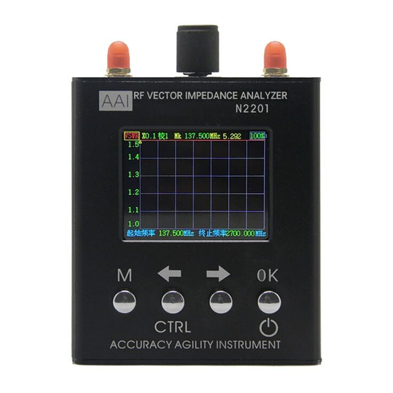
Page 5: Body Description
Body Description... - Page 6 Buttons and Interface Description Symbol Name Function Description Press this button to switch the "Single Point Measurement" and "Scan Mode" interface; hold down Main Menu the CTRL key and press the M key to switch between "System Information" and "Calibration" interface.
-
Page 7: Function Description
Function Description There are four basic operational interfaces including Single Point Measurement, Scan Function, Power meter Measurement , System Information and Calibration. The default interface after power-on is Single Point Measurement. 1. Single Point Measurement This interface is used for measuring the fixed frequency point. Only frequency parameters can be adjusted in this interface. -
Page 8: Scan Function
2. Scan Function Press M key under Single Point Measurement mode, it will switch to the Scan Function interface. Five type parameters of Scan Function can be modified. Scan Parameters Types: There are five scanning parameters including S11, VSWR,| Z|, R, X, Scaling: Scaling shows the Y-axis, and can be adjusted based on the measured value Mark Points Frequency: Scan mark points frequency of the graphic... - Page 9 will switch to Adjusting Mode, the red box of the selected parameter (Scan Parameters Types or Scaling) will turn to yellow; one of the digit of parameter (Start Frequency, Ending Frequency and Mark Points Frequency) will turn red. The method of adjusting parameter here is as same as that in Single Point Measurement: Select digit by pressing Right/Left key, modify the value by turning the knob(Knob button can be pressed as well, and the function of which is the same as OK key, when...
-
Page 10: Power Measuring
3. Power measuring △ Ensure that the power of input the power meter is not more than 10dBm! The PowerMeter can only measure directly small power (<10dBm,that is<10mW),When Power is more than 10mW, it needs to be used with the attenuator or coupler to ensure that the power of entering the PowerMeter is not more than 10mW. - Page 11 In addition, when the attenuator is used, the power and heat dissipation of the attenuator must be confirmed. At least 10W or more power attenuators are used for 5W signals. As shown in the following figure At this time N2201SS input power is 7dBm, maximum attenuator 30dB...
- Page 12 Change the measurement frequency and offset by OK key The results of different frequency measurements are different, so it needs set to the specified frequency. Different frequency measurement results will have differences, so it is basically set to the specified frequency. "offset" is used when correcting errors or converting external attenuators or amplifiers.
-
Page 13: System Information
4. System Information In Single Frequency mode or Scan Function interface, hold down the CTRL key (left), then press the M key, you can switch to the System Information interface. System information is mainly about the product, among which, automatic Power-Off parameter can be modified by turning the knob or pressing the Left/Right key. - Page 14 Special Attention: Red "CAL 0" marked on the product means using the system calibration parameters, that is the calibrated port is just at the RF port of the product. "CAL 1" means using the user calibration data. If using adapter, in the case of low frequency, there is no need to do calibration.
- Page 15 Correction Option located in the upper left side of the interface, and there are two options for now, one is "System Correction", the other is "User Correction ". When selecting “System Correction”, the measurement standard is at the SMA port of the product. Calibration Option located in the lower left side of the interface.
- Page 16 The calibration process takes times Followed by short-circuit calibration There is a preparation process and then it will show a prompt message “SHORT CAL”, Please connect the SHORT CAL and press the left button to start calibration.
- Page 17 Followed by standard load calibration There is a preparation process and then it will show a prompt message “LOAD CAL”, Please connect the LOAD CAL and press the left button to start calibration. All calibration is done Note: For user convenience, the Correction Option is automatically...
-
Page 18: Security Requirements
changed to User Correction during every calibration. At the same time, in order to ensure the integrity of the calibration, automatic power-off function is invalid and the device will keep power-on. Security Requirements 1. Charge This device is not equipped with charger, please use mobile phone or tablet charger with current 1A or more to charge. -
Page 19: Transport
3. Transport Shockproof and drop packaging are necessary in transport. Within batteries, we kindly recommend land or water transportation. Cautions 1. In order to ensure the accuracy of the measurement and calibration, please preheat the product for at least 5 minutes, especially when calibrating, preheating will make it more accurate. -
Page 20: After-Sales Service
After-sales Service After the product is sold, the product cannot work normally as its own problem within one year .AAI offers free maintenance or replacement service. AAI provides lifelong technical support as well. Contact us AAI commit to provide lifelong technical support for our product. Should...
Need help?
Do you have a question about the N2201SS and is the answer not in the manual?
Questions and answers