
Related Manuals for Metek MRR-2

Summary of Contents for Metek MRR-2
- Page 1 MRR-2 Micro Rain RADAR User Manual 10.2010 Valid for MRR Service Version ≥ 5.2.0.9...
- Page 2 Copyright: © 2010 METEK GmbH All Rights reserved. No part of this manual may be reproduced, transmitted, stored in a retrieval system, nor translated into any human or computer lan- guage, in any form or by any means, electronic, mechanical, optical, chemical, manual, or otherwise, without the prior written permission of the copyright owner.
-
Page 3: Table Of Contents
METEK Micro Rain Radar MRR-2 Table of Contents Safety Precautions ................3 How to use this manual ............... 5 Measuring Principle ................6 System Description ................7 Overview ....................7 Description of the Components ............10 4.2.1 Parabolic Dish ................... 10 4.2.2... - Page 4 METEK Micro Rain Radar MRR-2 6.4.2 Example .................... 40 Removing of the Software ..............41 Detailed description of the MRR-2 control program......41 Communication-, Data-, and Error-Service (CDES) ......42 7.1.1 Communication Service ..............42 7.1.2 Data Recording ................. 42 7.1.3...
-
Page 5: Safety Precautions
Micro Rain Radar MRR-2 1 Safety Precautions To operate the MRR-2 a mains voltage of 210-240 VAC is needed for the power supply. An improper handling can be dangerous to you. Only competent and instructed persons should work with this system or with parts of it. -
Page 7: How To Use This Manual
METEK Micro Rain Radar MRR-2 2 How to use this manual The delivered hardware items are described in section 4. Make sure that the delivery is complete and free of damage. Consult section 5 for setting up the hardware. In section 6 the installation and use of the control software is de- scribed. -
Page 8: Measuring Principle
Micro Rain Radar MRR-2 3 Measuring Principle The Micro Rain Radar MRR-2 retrieves quantitative rain rates, drop size dis- tributions, radar reflectivity, fall velocity of hydro meteors and other rain pa- rameters simultaneously on vertical profiles up to several kilometers above the radar. -
Page 9: System Description
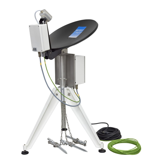
M ET E K M ic ro R a i n Ra d ar M R R - 2 4 System Description 4.1 Overview 10.2010 Valid for MRR Service Version ≥ 5.2.0.9... - Page 10 M ET E K M ic ro R a i n Ra d ar M R R - 2 Figure 1: Components of the System 1. Parabolic Dish, Case can vary 2. Transceiver, 3. RCPD, 4. Junction Box, 5. Cable Junction Box-PC, 6.
- Page 11 M ET E K M ic ro R a i n Ra d ar M R R - 2 The Control- and Evaluation Computer, a commercial PC, (not part of delivery) must be ordered separately. The operating system must be Windows® 2000 or XP.
-
Page 12: Description Of The Components
M ET E K M ic r o R a i n Ra d ar M R R - 2 4.2 Description of the Components 4.2.1 Parabolic Dish The antenna is used for the transmission of the RADAR signals and the re- ceiving of backscattered signals. -
Page 13: Junction Box / Power Supply
M ET E K M ic ro R a i n Ra d ar M R R - 2 The RCPD (3) gener- ates RADAR transmit modulation signal and passes it to the transceiver (2) through cable (15). It analyses backscattered receiv- er signal, calculates Doppler spectra and... - Page 14 M ET E K M ic r o R a i n Ra d ar M R R - 2 Figure 4: Junction Box Left:Front Side, Right: Back Side The junction box is used to pass through the communication between the PC and the RCPD.
-
Page 15: Cable Rcpd-Junction Box
M ET E K M ic ro R a i n Ra d ar M R R - 2 4.2.5 Cable RCPD-Junction Box Figure 5: Cable between Junction Box and RCPD The cable has a length of 25 m, on both ends are screwed plugs (male and female respectively). -
Page 16: Control- And Evaluation Computer (Pc)
Pin 7 ground The control program which is needed to operate the MRR-2 is part of delivery. Its installation and operation is described in section 6 Control Program page 18. 10.2010 Valid for MRR Service Version ≥ 5.2.0.9... -
Page 17: Hardware Installation
If measurements at very low heights are planned, (with appropriate settings the MRR-2 allows measurements from a minimum height of 20 m above ground) take care that the wind field in this level is not disturbed by nearby buildings, trees, masts etc., because strong turbulence could falsify the data. -
Page 18: Installation Procedure
A fixed vertical pole (Ø max. 49 mm, length min. 30 cm) is required for attach- ing the antenna. Operating of the MRR-2 requires a 230 VAC mains supply, with a fuse protection of 8 A (slow) minimum. To prevent disturbance of the device by variations or breaks of the power supply we recommend the use of a no-break power supply (UPS). - Page 19 Connect cable (5) to that serial interface of the computer, which was se- lected in the operating system for the connection of the MRR-2. If this se- rial port is unknown, it can be looked up in the administration of the "ser- vices"...
-
Page 20: Control Program
M ic r o R a i n Ra d ar M R R - 2 6 Control Program If the PC for controlling the MRR-2 with was not ordered separately the programs for controlling the MRR-2 and for data recording are delivered on a CD-ROM and must be installed on a PC with operating system Windows®... - Page 21 M ic ro R a i n Ra d ar M R R - 2 Figure 9: Login Screen If you are sitting at the PC which is directly connected to the MRR-2 leave the entry at Name of the Remote PC empty (or type a period or the name of the local PC).
- Page 22 M ic r o R a i n Ra d ar M R R - 2 If the connection to the communication service could be built up, the entire status of the MRR-2 is read out first. This can take some seconds, on RAS connections even some minutes.
-
Page 23: Main Menu
M ET E K M ic ro R a i n Ra d ar M R R - 2 6.2.1 Main Menu Figure 10: Main Menu The main menu shows buttons for the menus Control chapter 6.2.2 on page 22 Output Parameters chapter 6.2.3 on page 22 Device Parameters... -
Page 24: Control Commands Menu
10 min. Reset Pressing this button will perform a reset of the RCPD firmware. There is no influence on the MRR-2 parameters. It has the same effect as an interruption of the pow- er supply. 6.2.3 Output Parameters Menu Figure 12: Output Parameters 10.2010 Valid for MRR Service Version ≥... - Page 25 M ET E K M ic ro R a i n Ra d ar M R R - 2 The two upper panels shown in Figure 12 contain check boxes for configuring selections of averaged data and instantaneous data separately for recording. Instantaneous data are processed on the basis of one raw spectrum .
- Page 26 M ET E K M ic r o R a i n Ra d ar M R R - 2 Recording Options Raw data By checking “Record raw data” the raw spectra including metadata are written in addition to other selected data to a separate log-file. The path name of the- se log-files is defined by the parameters RawDataFile , RawDataPath.
-
Page 27: Device Parameters Menu
10 s time intervals within each averaging interval. Device Location ASL Enter the height of the MRR-2 location above sea level. The adjustable range is 0 ... 9999 m. This parameter is used for the density correction of the fall speed versus drop size relation. - Page 28 M ic r o R a i n Ra d ar M R R - 2 Sampling Frequency Number of samples per second of the analogue input signal of the MRR-2. This parameter can‟t be changed by the user. Calibration Constant This constant is needed for converting the engineering units of the receiver signal (raw data) into physical units (instantaneous and averaged data).
-
Page 29: Parameter Storage
M ic ro R a i n Ra d ar M R R - 2 6.2.5 Parameter Storage Figure 14: Parameter Storage Parameter Sets The parameter memory of the MRR-2 is used for convenient saving and load- ing of complete parameter settings. A parameter set consists of the device parameters (except calibration constant) and... - Page 30 M ET E K M ic r o R a i n Ra d ar M R R - 2 Deleting a parameter set: Type a name of the Parameter Sets list in the field right of the Save- button or select a name of the Parameter Sets list.
-
Page 31: Status Messages And Time-Axis Control
M ET E K M ic ro R a i n Ra d ar M R R - 2 6.2.6 Status messages and time-axis control Figure 15: System Status Sub-Panel: “State of the MRR Service Program” The version number of the MRR service program is shown. The operation state is shown: ... - Page 32 M ET E K M ic r o R a i n Ra d ar M R R - 2 Sub-Panel: “Data Recording” Disk capacity exhausted in The remaining time for data recording is shown. The calculation is based on the average sizes of the last re- ceived measuring protocol and the actual free disk space (Initially ??? ap- pears until the first data set is stored).
-
Page 33: Instantaneous And Averaged Data
(see chapter 7.1.2 Data Recording on page 42). Optional recording of so called raw data, which represent the unprocessed measuring data of the MRR-2, is only useful for special purposes. The data format is human readable ASCII text. Each data set consists of one line. - Page 34 M ET E K M ic r o R a i n Ra d ar M R R - 2 in increments according to the chosen height resolution of the MRR. Invalid or not calculable values are coded as 7 consecutive space characters. Space characters at the end of a line are omitted in order to save disk space.
- Page 35 M ET E K M ic ro R a i n Ra d ar M R R - 2 Example (Each entry of the header line is shown in a separate line of the ta- The header line dates from June 12 , 2009, 4:02 AM, UTC.
- Page 36 M ET E K M ic r o R a i n Ra d ar M R R - 2 of frequency-bin-index nn to diameter D is listed explicitly for each bin and height. The center of each size class is displayed. Nnn with nn from min(h) to max(h) - Spectral Drop Densities With the knowledge of the frequency of the Doppler-shift the calculation of the corresponding drop fall velocity is possible (equation 1.4.3.2 in MRR Physical...
- Page 37 M ET E K M ic ro R a i n Ra d ar M R R - 2 W - Fall Velocity W is the characteristic falling velocity. (First Moment of the Doppler spectrum, see chapter 3.4 MRR-Physical Ba- sics).
-
Page 38: Example
M ET E K M ic ro R a i n Ra d ar M R R - 2 6.3.2 Example Instantaneous and averaged data files have the same structure including the header lines, except of the entry AVE, which is missing in the instantaneous data. - Page 39 M ET E K M ic ro R a i n Ra d ar M R R - 2 F59-101.35-109.38 -106.55 -94.94 -93.66 -89.85 -93.59 -89.22 -86.48 -92.83 -89.13 -88.15 -87.38 -86.91 -86.30 -87.35 -84.84 -84.90 -86.03 -88.15 -83.88 -81.63 -82.16 -80.38 -78.67 -78.18 -77.11 -78.68 -78.96 F60 -97.25 -98.23-106.60-102.53-108.97 -94.12 -93.94 -91.66 -92.15 -87.70 -91.76 -87.39 -86.05 -86.21 -86.36 -85.50 -86.28 -84.29 -84.31 -84.44 -87.38 -84.13 -81.27 -80.91 -79.17 -77.69 -77.71 -76.41 -77.96 -79.56 F61 -85.64 -91.97 -96.80 -97.21-106.05 -94.75 -93.78 -92.73...
- Page 40 M ET E K M ic ro R a i n Ra d ar M R R - 2 65034 77233 77047 54277 54943 63194 75355 64328 66657 72639 68916 70825 60905 62989 65385 56005 46039 40390 37312 35709 33954 36990 49099 65355...
-
Page 41: Raw Data
M ET E K M ic ro R a i n Ra d ar M R R - 2 6.4 Raw data 6.4.1 Format Description Each data block in a raw data file begins with a header line which contains the date, the time and the time zone of the following data block. -
Page 42: Example
M ET E K M ic ro R a i n Ra d ar M R R - 2 6.4.2 Example T:090612024311 UTC DVS 5.10 DSN 020704 CC 2066000 MDQ 100 58 58 1015 1050 1085 M:TF = 0.003292 0.011523 0.041975 0.099863 0.175583 0.254184 0.334019 0.425514 0.532373 0.603018 0.675720 0.756516 0.794239 0.836626 0.877778 0.891358 1.000000 0.968313 0.924280 0.883813 0.890398 0.903978 0.875857 0.853772 0.843347 0.834568 0.780658 0.774897 0.752401 0.689026 0.640604 0.422497 M:f00= 4798 2205... -
Page 43: Removing Of The Software
Device (RCPD) at the antenna. The measured data are transmitted by a serial RS-232 port. This port is also used for the device control. If the MRR-2 is connected to a PC, the control, the calculation of further values, and the re- cording of the data can be done with the MRR-2-control program described below. -
Page 44: Communication-, Data-, And Error-Service (Cdes)
(CPUI) and the control port of the MRR-2, which is implemented as a serial interface. With CDES the system settings of the MRR-2 can be re- trieved and any changes entered by the user are translated to the correspond- ing commands and transmitted to the MRR-2. -
Page 45: Error Protocol
7.1.3 Error Protocol The third function of CDES is the recording of all error messages which are caused by the operation of the MRR-2 (except messages which are generated from user input errors). The error recording is done by the event logging function of the operation sys- tem. -
Page 46: Control Program User Interface (Cpui)
RAS connection. The communication of the user interface on PC #2 with the MRR-2 uses the network and the communica- tion service program on PC #1. The data recording and the event logging is... - Page 47 M ET E K M ic ro R a i n Ra d ar M R R - 2 The software is supplied on a CD-ROM with the following files: MrrSrvc.exe the service program MrrCtrl.exe control program (GUI) Messages.dll used for error messaging MFC71.dll used for runtime environment msvcr71.dll...
- Page 48 M ET E K M ic r o R a i n Ra d ar M R R - 2 The port variables of this key are shown with their default settings. Change the underlined values, if necessary : Port REG_SZ COM2 BaudRate...
-
Page 49: Mrr-2 Specifications
M ET E K M ic ro R a i n Ra d ar M R R - 2 8 MRR-2 Specifications RCPD with Radar module Operating Frequency: 24.230 GHz Operating Mode: FMCW Modulation: 1.5 - 15 MHz Output Power: 50 mW (+17 dBm) (antenna foot point) OoB and Spurious Emission: <... - Page 50 M ET E K M ic r o R a i n Ra d ar M R R - 2 10.2010 Valid for MRR Service Version ≥ 5.2.0.9...
Need help?
Do you have a question about the MRR-2 and is the answer not in the manual?
Questions and answers