Advertisement
Quick Links
Advertisement

Summary of Contents for Abbey Machinery VF1500T
- Page 1 Vertical Auger TUB FEEDER All Models...
- Page 2 Abbey Tub Feeder P.D.I Chart This Dealer pre-delivery inspection chart is to be completed and signed by the dealer or their representative before the machine is supplied to the customer. Model______________________Date_________________Serial No_____________________ Tick box below after item is checked. All Models Check all hydraulic connections.
- Page 3 INSTRUCTION MANUAL CONTENTS Section No. Page No. The function of the Tub Feeder. Abbey Tub Feeder Safety warning. Abbey Tub Feeder setting up for use. Abbey Tub Feeder operating instructions. Tub Feeder care and maintenance. Pre Season Abbey Tub Feeder Maintenance. Replacement Parts.
- Page 4 Suggested Max MODEL No Load Weights tonnes TUB FEEDER SINGLE AUGER MODELS VF 850 VF 950 /VF1000 VF 1050 VF 1250 VF 1450 TWIN AUGER MODELS VF 1500 TWIN VF 1650 VF 1850 VF 2100 VF 2250 VF 2450 10.2 VF 2650 VF 2850 11.8...
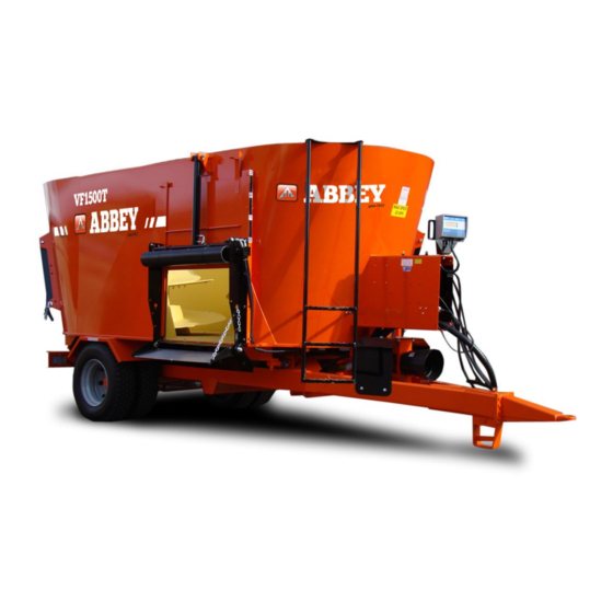
- Page 5 The Range of Abbey Diet Feeders includes 100 CD, 145 GD The Range of Abbey Vertical Augur Tub Feeders includes VF Single 750, 800, 1000, 1050, 1250, 1450, VF Twin 1500, 1650, 1850. 2050. 2250, 2450, 2650, 2850 THE FUNCTION OF THE TUB FEEDER The Abbey Tub Feeder is a trailed machine which is capable of independently mixing, transporting and feeding set weights of ingredients to make a complete diet for cattle.
-
Page 6: Safety Warning
Abbey Tub Feeders 2.0 SAFETY WARNING 1. Always ensure that before operating the machine both the feeder guards and PTO shield are in place.PTO shields and feeder covers should be properly maintained and must always be replaced after carrying out adjustments or repairs. 2. - Page 7 Abbey Tub Feeders 2.0 SAFETY WARNING (cont’d) 14. The PTO shaft of the machine is to be left on the stand provided, when the machine is not in use to prevent the shaft guard from being damaged. 15. If you have any doubt as to the safe operation or maintenance of your Tub Feeder contact your local dealer.
-
Page 8: Setting Up For Use
Abbey Tub Feeders SETTING UP FOR USE 1. Connect the Tub Feeder to the tractor pick-up hitch or drawbar. If connected to the tractor drawbar the optional necessary hitch eye reducer bush must be used. Measure the P1’O shaft of the machine and ensure that it is fitted according to its instructions. - Page 9 Abbey Tub Feeders SETTING UP FOR USE– Wiring...
- Page 10 Abbey Tub Feeders SETTING UP FOR USE– Wiring We wire the indicator clock up to the lights junction box on the machine. Below is the Wiring diagram. Once side lights are turned on, there is power to the indicator.
- Page 11 Abbey Tub Feeders SETTING UP FOR USE– Wiring...
- Page 12 AbbeyTub Feeders 4.0 OPERATING INSTRUCTIONS Before operating the Tub Feeder ensure that you and all operators of the machine are familiar with the safety warnings in this manual. Connect all the necessary hydraulic hoses and electrical plugs to the tractor. If you are not familiar with the electronic weighing system of the feeder please read the accompanying Digi-Star Electronics operators manual.
- Page 13 Abbey Tub Feeders 4.0 OPERATING INSTRUCTIONS (Contd). UNLOADING 1. Select the desired unloading program. 2. Lower the elevator (if fitted) to the correct unloading height and start the conveyor & elevator running in the correct direction. 3. Adjust the speed of the conveyor and open the door of the feeder the required amount as indicated by the scale on the door.
- Page 14 Abbey Tub Feeders 4.0 OPERATING INSTRUCTIONS (Cont’d). USEFUL ADVICE ON TUB FEEDERS Chopping baled silage to a length of 5-10cm or shorter will give the best mix and unloading performance. Check that no foreign objects have been allowed into the mix, these may cause damage to livestock or machinery.
-
Page 15: Care And Maintenance
Abbey Tub Feeders 5.0 CARE AND MAINTENANCE 1. Grease should be applied to all grease points at regular intervals during the working season on the machine. (A suggested interval would be every 7 days). 2. Before maintaining any part under the machine always support the machine mixing tub with suitable stands. - Page 16 Abbey Tub Feeders 5.0 CARE AND MAINTENANCE (Contd) Check after the first 10 hours of use: - Weigh bar and chassis bolts are tight. - Wheel nuts and bearings are tight. Check Monthly: - Conveyor chain tension and adjust if necessary - All grease points.
- Page 17 Abbey Tub Feeders 5.0 CARE AND MAINTENANCE (Contd) Instructions on dismantling a belt Elevator Loosen flange bearing bolts on both rollers. Four in total Loosen tensioner bolts so the roller is free to slide up and down on both sides. ...
- Page 18 Abbey Tub Feeders 5.0 CARE AND MAINTENANCE (Contd) Instructions on assembling the belt Place belt around both rollers and match up joiners Fit new belt joiner cable. Square up rollers on frame. Tension both roller tensioners on each roller (Note: rollers should only be tightened until the roller starts to turn the belt.
- Page 19 Abbey Tub Feeders 5.0 CARE AND MAINTENCE (Contd). Service Intervals First 300hrs/ 1000hrs/ Daily Weekly 100hr's Season Season √ Grease universal joints on each end of P.T.O. shaft. √ Check Gearbox Oil level. √ √ Change Gearbox oil Check tightness of gearbox bolts. Ref Page 21. √...
- Page 20 Abbey Tub Feeders 5.0 CARE AND MAINTENCE (Contd). Changing the Gearbox Oil (Planetary Gearbox) Period First at 100 hours Thereafter, every 1000 working hours or at least once per season. Oil type and quantity: 85 W140 and 18 litres minimum for each planetary gearbox. 1.
- Page 21 Abbey Tub Feeders 5.0 CARE AND MAINTENCE (Contd). Procedure on changing wheel: 1. Call a tyre company to fix/replace the wheel. (These companies are professionals with proper lifting equipment and can have the wheel replaced or fixed on site) If this is not possible: 2.
- Page 22 VF TUBS GEARBOX BOLT ASSEMBLY PROCEDURE Nord Lock Washer TUB BASE Nord Lock Washer Gearbox Standard Washer VF800 and VF1500 M14 x 180s - Grade 12.9 Bolts, M14 Washers, Gasket ABY-VF1201.213 and M14 - Grade 10 Nuts. The bolt head goes underneath the machine and the nut and nord lock washer are on top inside the barrel.
- Page 23 Abbey Tub Feeders 5.1 PRE SEASON ABBEY TUB FEEDER MAINTENANCE Grease all points on the machine at regular intervals throughout the Season (a suggested period is once every 7 days). Grease the PTO shafts as recommended on their respective instruction booklets. If a conveyor is fitted to the machine grease all points and oil the conveyor chain well for the best performance.
- Page 24 Abbey Tub Feeders 6.0 REPLACEMENT PARTS TWIN DOOR TUB - AM PARTS Pos. Description Qty. Part No. Pos. Description Qty. Part No. PIN 1” X 4”+ Linch Pin M8X20 Bolt + L-Nut DIN933-M8X20 ABY9145 Junction Box ABY9881 A Door Ram ABY4927 PIN 1”...
-
Page 25: Replacement Parts
Abbey Tub Feeders 6.0 REPLACEMENT PARTS TWIN REAR DOOR TUB - AF PARTS Pos. Description Qty. Part No. Pos. Description Qty. Part No. Door Indicator Channel ABY 9969 Tub Main Body ABY9812 Door Indicator ABY 9970 Std Ladder ABY9813 Piano Hinge ABY 9876 Twin Tub Ladder ABY9813T... - Page 26 Abbey Tub Feeders 6.0 REPLACEMENT PARTS REAR MEAL DOOR Description Part No Rear Door light Bracket Left and Right ABY9504 Rear Door Left Side Panel left ABY9806-L-MD Rear Door Tray ABY9801-MD Rear Door Stainless ABY9802-MD Top Ram Pin ABY 9194 Bottom Ram Pin ABY 9145 Rear Door Right Side Panel Right...
- Page 27 Abbey Tub Feeders 6.0 REPLACEMENT PARTS SIDE DOOR TUB – AF PARTS Pos. Description Qty. Part No. Pos. Description Qty. Part No. Tub Main Body ABY9812 Counter Blade ABY9810 Digital Indicator Mt Bracket ABY 9971 Door Rails ABY9800 Ladder ABY9813 Tray Hinge Angle Left ABY 9850-L Twin Tub Ladder...
- Page 28 Abbey Tub Feeders 6.0 REPLACEMENT PARTS SIDE DOOR TUB – AM PARTS Pos. Description Qty. Part No. Pos. Description Qty. Part No. M6x20 Din933-M6x20 M12x60 Cuphead+L-Nut DIN4.6-M12X60 Digital Indicator ABY9880 A M10x25 Cuphead+L-Nut DIN4.6-M10X25 M12x30+L-Nut Din933-M12x30 M16x50 + L-Nut Din933-M16X50 M10X30+L-Nut+ Washer Din933-M10x30 M8x20 Cuphead+L-Nut...
- Page 29 Abbey Tub Feeders 6.0 REPLACEMENT PARTS DIAGONAL DOOR TUB – AM PARTS Pos. Description Qty. Part No. Pos. Description Qty. Part No. Circlip CLP 28mm-E M8 x 20 + L-Nut Din933-M8X20 Counter Blade Hinge Pin ABY 9809 Junction Box ABY9881 A Counter Blade Locking Pin ABY 9811 M6x20 + L-Nuts + Washer...
- Page 30 Abbey Tub Feeders 6.0 REPLACEMENT PARTS DIAGONAL DOOR TUB – AF PARTS Pos. Description Qty. Part No. Pos. Description Qty. Part No. Counter Blade ABY 9810 Oil Reservoir ABY 9815 Door Rails ABY 9800 Front Side Panel VF10 ABY 9816 Door Rubber Hinge Angle ABY 9803 Ladder Short Stay Bar...
- Page 31 Abbey Tub Feeders 6.0 REPLACEMENT PARTS 2 SPEED TUB FEEDER DRIVE LINE Pos. Description Qty. Part No. Pos. Description Qty. Part No. T60 PTO Shaft COM0763311610 M16 x 70 + F-Washer Din 933-M16 x 70 M8X25 + F-Washer Din 933-M8 x 25 Auger Knifes ABY 9949 Shaft Guard...
- Page 32 Abbey Tub Feeders 6.0 REPLACEMENT PARTS SINGLE SPEED TUB FEEDER DRIVE LINE Pos. Description Qty. Part No. Pos. Description Qty. Part No. T60 PTO Shaft COM0763310710 Auger Knifes ABY 9949 M14X40 + F-Washer Din 933-M14 x 40 M10 x 40+L-Nut+Washers Din 933-M10x40 35MM Flange Bearing BRNUCF 207E...
- Page 33 Abbey Tub Feeders 6.0 REPLACEMENT PARTS VF12 TUB PART – AF & AM PARTS Pos. Description Qty. Part No. Pos. Description Qty. Part No. VF12 Ladder ABY 9814 Counter Blade Locking Pin ABY 9811 M8x20 + L-Nut Din933-M8 x 20 Counter Blade ABY 9810 Digital Indicator...
- Page 34 Abbey Tub Feeders 6.0 REPLACEMENT PARTS CONVEYOR PARTS – AF & AM PARTS Pos. Description Qty. Part No. Pos. Description Qty. Part No. 1 1/8” Flange Bearing Hydraulic Motor ABY 6998 BRNUCF206E-18 M12x40 + L-Nut Din933-M12x40 M16 Threaded Tensioner Din 975-M16B8 Motor Mounting Cover ABY 6997 M8 x 20 + L-Nut...
- Page 35 Abbey Tub Feeders 6.0 REPLACEMENT PARTS Belt Conveyor – AF & AM PARTS Pos. Description Qty. Part No. Tensioner Plate ABY 9841 Motor ABY 7003 Bearings BRNUCF206E-18 Front Roller ABY 143 Back Roller ABY 144 Chassis (740mm) ABY 140 Belt (1425mm) ABY-21-11 Side Skirt Brush ABY-4-26-600...
- Page 36 Abbey Tub Feeders 6.0 REPLACEMENT PARTS Belt Conveyor Mounting Parts – AM PARTS Pos. Description Qty. Part No. 3-Hole Retaining Bar ABY 6947 Elevator Hinge Angle Left ABY 6950-R Elevator Hinge Angle Right ABY 6950-L PVC Elevator Ram Mounting Rail ABY 6948 Hydraulic Ram ABY 9768...
- Page 37 Abbey Tub Feeders 6.0 REPLACEMENT PARTS Slat & Chain Conveyor – AF & AM PARTS Pos. Description Qty. Part No. Pos. Description Qty. Part No. Lift and Lower Ram ABY 4929 Keys 8 x 7 x 40 KEYSK8X7X40 Conveyor Tray Backing ABY1049 Conveyor Chain Sprocket ABY 1043...
- Page 38 Abbey Tub Feeders 6.0 REPLACEMENT PARTS FD sliding PVC Conveyor – AF & AM PARTS Pos. Description Qty. Part No. Pos. Description Qty. Part No. Fixed frame SC ABYPVCSC0001 Hollow Pin Sliding Ram PIN28.5X65 Sliding Conveyor Frame ABYPVCSC0002 Sliding conveyor Ram ABY9768 Idler Roller SC PVC ABYPVCSC0003...
- Page 39 Abbey Tub Feeders 6.0 REPLACEMENT PARTS Rollers AM Parts Slats AM Parts Slat Length Type Part Number Side Door (Current) ABY9920Z Side Door (Old) ABY9920U Fixed Front Door ABY9844 Sliding Front Door ABY9844-S...
- Page 40 Abbey Tub Feeders 6.0 REPLACEMENT PARTS Feed Roller AM+AF Parts Pos. Description Qty. Part No. Pos. Description Qty. Part No. Door Lip Plate ABY 6952 MF80 Hydraulic Motor ABY 7003 10” Feed Roller ABY 6953 Hydraulic Ram ABY 9577 Bearing BRUNCF206E-18 15mm Bushing ABY6955...
- Page 41 Abbey Tub Feeders 6.0 REPLACEMENT PARTS Flat Top Rings AM Parts Pos. Description Qty. Part No. Flat Top Retaining Ring Straight ABY 6959 Flat Top retaining Ring Straight/Curve ABY 6960 Flat Top Retaining Ring Curve ABY 6961 ABY6959 ABY6960 ABY6961 Single Auger Set Twin Auger Set...
- Page 42 Abbey Tub Feeders 6.0 REPLACEMENT PARTS Beet Knives AM Parts...
- Page 43 Abbey Tub Feeders 6.0 REPLACEMENT PARTS TUB CHASSIS ASSEMBLY - AF PARTS Pos. Description Qty. Part No. Bolt-on Hitch ABY 1003 Stand Pin ABY 1004 Stand ABY 3507 Y-Bar ABY 9819 Gearbox Cover ABY 9820 Side Panel - Left ABY 9821 - L Side Panel- Right ABY 9821 - R Chassis Rear Panel...
- Page 44 Abbey Tub Feeders 6.0 REPLACEMENT PARTS TUB CHASSIS ASSEMBLY - AM PARTS Pos. Description Qty. Part No. Pos. Description Qty. Part No. M16 x 40 + L-Nut Din 933-M16 x 40 R-Clip 4mm CLP 3553 M16 x 40 + L-Nut Din 933-M16x40 M10 x 25 + L-Nut DIN 933-M10x25...
- Page 45 Abbey Tub Feeders 6.0 REPLACEMENT PARTS Axle 350X60 & 300X60 Braked - AF PARTS Item No: Description Part No: 350X60 Part No: 300X50 Brake Assembly ADR9RE0014 ADR99R0008 Camshaft ADR9RE0014 ADR99R0008 Retaining Ring ADR9RE0014 ADR99R0008 Washer ADR9RE0014 ADR99R0008 M24x1,5 ADR9RE0014 ADR99R0008 Spring ADR9RK0004 ADR99R0008...
- Page 46 Tandem Bogie...
- Page 47 Tandem Axle Steering Boggie...
-
Page 48: Cable Controls
Cable Controls Kit Number=ABY9982 No. Qty. Part No. Description H-03P40A1X3GKZ1 3/8” 3 Bank Valve Chest FB-0099.21.24.02 3 Section Actuator kit FB-0099.30.36.51 P40 Fitting Kit3/8”Badestnost FB-1501-1003 Single Actuator for cables FB-971630-03000 3m Cable H-P40-8 Detent Kit... - Page 50 Notes...
- Page 51 Notes...
-
Page 53: Warranty
Abbey Tub Feeders 7.0 WARRANTY The following warranty terms relate to parts only. Abbey Machinery LTD will not accept claims for labour or mileage. 1. This Tub Feeder is covered by the manufactures warranty for twelve months or one season. -
Page 54: Terms And Conditions Of Sale
8.0 Terms and Conditions of Sale General Consideration: Abbey Machinery Ltd, shall hereinafter be referred to as “the Company”. All products and/or components or whatever kind and all services sold by the company shall be sold subject to these Terms & Conditions of Sale and shall hereinafter be referred to as “the Goods”. - Page 55 Repairs and Alterations Any products accepted for repair or alterations by the Company shall be held by the Company and repaired and altered by it entirely at Customer’s own risk. Force Majeure If circumstances occur which could not have been foreseen at the time the contract was concluded and which are beyond the control of the company and directly or indirectly prevent, hinder or make more difficult the full or partial performance of the contract, such circumstances being, inter alia war, threat of war, civil war, natural disasters, riots, strikes, lockouts, fire, breakdowns in the Company’s factory, delayed or incorrect deliveries by...
Need help?
Do you have a question about the VF1500T and is the answer not in the manual?
Questions and answers