
Related Manuals for KENT KGS818AH

Summary of Contents for KENT KGS818AH
-
Page 1: Model:kgs818Ah/Ahd
INSTRUCTION MANUAL FOR PRECISION SURFACE GRINDER MODEL:KGS818AH/AHD KGS1020AH/AHD KENT INDUSTRIAL (U.S.A.) INC... -
Page 2: Chapter One Installation Guidelines
Chapter One Installation Guidelines General Safety Rules 1. The employer must select trained and qualified personnel to operate machinery. 2. The employer must adhere to local national safety laws and regulations when teaching operators safety and cleanly procedures. 3. The employer must inform operators to look out for unsafe operating practices. 4. - Page 3 2. Combustible liquids must not be used as a cutting liquid. 3. The machine should not be used to grind lumber, plastic, or other combustible materials. Please contact KENT Industrial Co, Ltd. if you wish to use optional or special equipment provided by the company to grind graphite or porcelain.
- Page 4 not use grinding wheels that do not conform to listed specifications or work pieces that are excessively large or heavy. 6. To avoid the risk of an accident, the user should not modify the electrical circuitry without prior authorization. 7. Do not change interlocking circuits into bypass circuits. 8.
-
Page 5: Table Of Contents
CONTENTS MODEL:KGS818AH/AHD ..................1 Chapter One Installation Guidelines ................2 CONTENTS ......................5 Transit .........................7 Unpacking ......................7 Packing Diagram ....................8 Choice of Site ......................8 Installation ......................9 (1).Power Consumption..................9 (2).Foundation (Use the leveling pads and screws) ..........9 (3).Contour and Name of Components ............... 10 (4).Cleaning Up the Machine ................ - Page 6 Grinding ......................28 Wheel Inspection ....................28 Dressing The Wheel And Correct Treatment Of Dressing Diamond ....29 Storage of Grinding Wheel ................31 Selection of Suitable Grinding Wheels ............... 31 Wheel to Be Recommended ................33 Choice of The Grinding Condition ..............33 Use of the Optional Attachment .................
-
Page 7: A) Transit
THIS MACHINE HAS BEEN FULLY TESTED, ADJUSTED, AND INSPECTED FOR CORRECT ALIGNMENT AND OPERATION. PRIOR TO SHIPMENT, IN TRANSIT, OR INSTALLATION, PLEASE ENSURE THAT THE MACHINE IS NOT BUMPED WHEN BEING ROLLED OR SET DOWN TO AVOID ANY FAILURE. Transit By Fork Lift By Hoist or Chain Block Heavy End... -
Page 8: Packing Diagram
(1) Packing Diagram 1. Machine 2. standard Accessories 3. Coolant Tank 4. Table and Splash Guard Choice of Site The output of the machine and the degree of accuracy of the components produced depend on the correct choice of site for the position of the machine. Grinding machines are often found between milling, shaping, drilling and even slotting machines, without any thought of the consequences of such planning. -
Page 9: D) Installation
Dust Collection Crossfeed Spindle Coolant Hydraulic Motor Motor Motor Motor Motor KGS818AH/AHD 1.5KW 1.5KW 550W 2.2KW 1.5KW 550W KGS1020AH/AHD (2).Foundation (Use the leveling pads and screws) * Lower the machine slowly into position. * Insert the leveling pad into the hole of the machine base. -
Page 10: Contour And Name Of Components
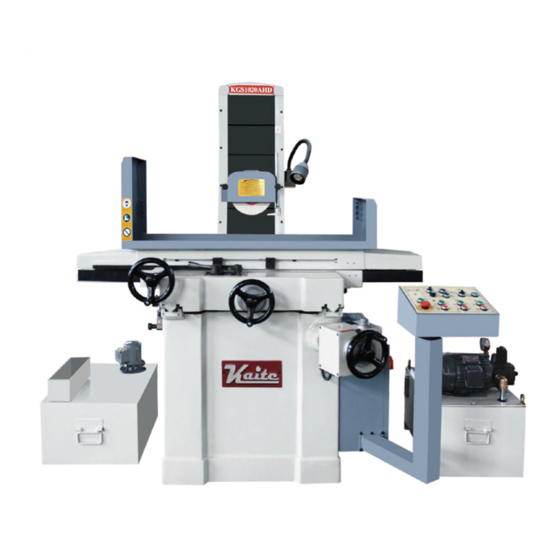
(3).Contour and Name of Components Spindle Motor Flow Lever (Auto.) Hand Wheel Downfeed (Crossfeed) Gear Box Hand Wheel (Longitudinal) Column Electric Hand Wheel (Vertical) Control Box Wheel Guard Grinding Wheel Dog(Right) Saddle Dog(Left) Table Lifting Stud Electric Cabinet... -
Page 11: Cleaning Up The Machine
(4).Cleaning Up the Machine This machine has been ensured moisture-proof, dust-proof, and rust-proof before packing. Please cleanup the machine before moving the longitudinal cross and up & down, otherwise it will affect grinding accuracy. 1.Guideway (5).Mounting the Table a. Mounting the table 1. -
Page 12: Leveling The Machine
(6).Leveling the Machine Procedure: a) Use longitudinal hand wheel to move table to the left end position. Level the machine by a Spirit Level in longitudinal and latitudinal direction (Fig.A). b) Use longitudinal hand wheel to move table to the right end position. Level the machine in the longitudinal and latitudinal direction (Fig.B). - Page 13 (7).Table size and movement scope a.KGS818AH/AHD MAX220 SPECIFICATION KGS818AH/AHD Size of working table 200mm×460mm Table traverse Longitudinal traverse 510mm Cross traverse 250mm Distance from spindle axis to table surface 70-530mm Spindle vertical traverse 460mm Wheel size 200mm×25mm×32mm Spindle motor 2850r/min 50HZ Overall dimension(L×W×H)
- Page 14 b.KGS1020AH/AHD MAX276 SPECIFICATION KGS1020AH/AHD Size of working table 250mm×510mm Table traverse Longitudinal traverse 575mm Cross traverse 280mm Distance from spindle axis to table surface 70-535mm Spindle vertical traverse 460mm Wheel size 200mm×25mm×32mm Spindle motor 2850r/min 50HZ Overall dimension(L×W×H) 1680mm×2030mm×2110mm...
-
Page 15: Lubrication
(8).Lubrication Lubrication Flow Chart Elevation slideways Saddle "V" groove Saddle plane groove PJ-4 Vertical leadscrew PJ-9S Crossfeed leadscrew Bed "V" right groove Bed "V" left groove PJ-7S Auto .lubrication pump Ⅲ MMXL- -6/5.5-AC220 Reliability and efficiency of the machine are ensured only by the correct choice of lubricant for the individual lubricating points. -
Page 16: Hydraulic System
(9).Hydraulic System a) Hydraulic Diagram Table Cylinder Control Valve Downfeed Cylinder Downfeed Solenoid Valve Clutch Engage Cylinder Clutch Engage Solenoid Valve Pressure Gauge Check Valve Hydraulic Pump Hydraulic Motor Hydraulic Tank Sequence Valve... - Page 17 b) Hydraulic Oil Hydraulic tank volume: 51.3 liters Re-fill frequency: After the first month, clean the hydraulic tank and change the oil every six months. Hydraulic oil: ESSO MOBIL MOBIL R-68 ENGRGOL ESSTIC 50 D.T.E OIL SHELL HL100 Medium Tellus oil 29 4.5 E/50 C 4.7 E/50 C 3.93 E/50 C...
-
Page 18: Limit Switch Position
(10).Limit Switch Position Description: Description: (1). Rear limit:SQ3 (1). Rear limit:SQ3 (2). Front limit:SQ2 (3). Rear reversal limit:SQ1 (2). Front limit:SQ2 (4). Front reversal limit:SQ4 (3). Rear reversal limit:SQ1 (5). Auto.down feed switch:SQ5 (6). Auto.cross feed switch:SQ6 (4). Front reversal limit:SQ4 For above-mentioned cord no.,please refer to Circuit Diagram. -
Page 19: Balancing The Grinding Wheel
(11).Balancing the Grinding Wheel Efficient balancing is essential in eliminating unnecessary stress in the wheel. It can also help obtain high quality surface finishes, grinding accuracy, and extend the life of the grinding wheel. In this case, the grinding wheel has to be balanced carefully. Static balancing can better meet the requirements of machining. - Page 20 After being balanced for the first time, the wheel must be mounted on the grinding spindle of the machine and dressed. This can be done with the parallel dresser on the spindle carrier or with one fitted on the table. When dressing the wheel from the table, the table must be locked longitudinally and then cross-traversed with the hand-wheel.
-
Page 21: E) Putting The Machine Into Operation
*If various materials have to be grounded, so that the wheel has to be changed frequently, it is more advantageous to change the wheel completely with a flange. It would save you time from removing the wheel from its mount each time to re-balance and re-dress it. Putting The Machine Into Operation (1).Wiring of power source Be sure that the wire connection is same as your power source before you power "ON"... - Page 22 For U.S.A area: 200V to 220V power source: Box B Box A U6 V6 W6 U V W Power Source 220V to 240V power source: Box B Box A U6 V6 W6 U V W Power Source 440V to 460V power source: Box B Box A U6 V6 W6...
-
Page 23: Control Panel &Description
(2).Control Panel &Description a.KGS1020AH/AHD SB1: Power"ON" SB2: Grinding wheel spindle "OFF" SB3: Grinding wheel spindle "ON" SB4: Hydraulic motor "OFF" SB5: Hydraulic motor "ON" SB6: Coolant motor "OFF" SB7: Coolant motor "ON" SB8: Emergency pushbutton SB13:Crossfeed away from operator "ON" SB15:Crossfeed approach to operator "ON"... - Page 24 SB18 SB19 SB1: Power"ON" SB2: Grinding wheel spindle "OFF" SB3: Grinding wheel spindle "ON" SB4: Hydraulic motor "OFF" SB5: Hydraulic motor "ON" SB6: Coolant motor "OFF" SB7: Coolant motor "ON" SB8: Emergency pushbutton SB13:Crossfeed away from operator "ON" SB15:Crossfeed approach to operator "ON"...
-
Page 25: Operation
(3) Operation a. Before operation It's only after the following instructions have been fully complied with that the machine can be started: 1. Choice of a location free from vibration. 2. Clean up the machine of those anti-rust oil and grease. 3. - Page 26 3).Cross travel 1.Turn SA1 to left, press SB13, saddle moves away from operator continuously; press SB15, saddle moves close to operator continuously. This function is only effective when SA1 is in left position (surface grinding), it can't start in right position for vertical feed grinding. 2.Turn SA1 to right, press SB15 or SB13 and release, adjust RP, the saddle feeds automatically when surface grinding.
- Page 27 3. For instance, total work piece down-feed removal is 0.02", and auto down-feed increment is to be set at 0.001": Loosen the set-screw on the graduation dial and turn the dial to let the Scale "0.08" aim at the mark "0"on the fixed indicator ring.(1 revolution of down-feed hand wheel is 0.1" minus total removal 0.02"...
-
Page 28: F) Grinding
Grinding The grinding results obtained depend to a very large degree on the choice of the correct grinding wheel and suitable operation. (1)Stock removal efficiency For intensive stock removal, a coarse grain(about 30-36)should be used. The wheel is dressed by passing the diamond over quickly so that the surface of the wheel is roughed and bites well. -
Page 29: H) Dressing The Wheel And Correct Treatment Of Dressing Diamond
Dressing The Wheel And Correct Treatment Of Dressing Diamond The diamond is inserted in the dressing device. The sleeve of the device is arranged at an angle of about 5°, so that, when the diamond loses its keenness, it can be turned in the sleeve, along with its holder, thus ensuring that there is always a sharp diamond edge available. - Page 30 Experience has shown that with highly accurate grinding, dressing with the hand operated dressing device on the spindle carrier is inadequate. The hand operation causes slight undulations to the surface of the wheel. ( ) ( ) ( ) ( )...
-
Page 31: I) Storage Of Grinding Wheel
Storage of Grinding Wheel The wheels should be kept in special racks in a dry place and must be protected from knocks and jolts, especially when they are being transported. As a rule, they should be stood on edge, but thin wheels and wheels with a sharp edge must be laid flat on an even surface. - Page 32 (c) Grade: It indicates the strength of the bond which hold abrasiveness. Soft: A to H Medium: I to P Hard: Q to Z Grade Soft Hard Grinding condition Workpiece hardness hard soft wide narrow Surface contacted quick slow Movement of work quick Wheel speed slow...
-
Page 33: K) Wheel To Be Recommended
Wheel to Be Recommended Wheel diameter Under 205mm 205 to 355mm Material be ground Under HRC25° Carbon steel WA 46J WA 46I Above HRC25° Under HRC55° Alloy steel Above HRC55° Under HRC60° Tool steel Above HRC60° Stainless steel C 46J C 46I Cast iron C 30J... - Page 34 (2).Cross feed Cross feed Great Small Grinding resitance great small Heat produced much less rough Surface finish fine Wheel worn out much little (3).Longitudinal feed Quick Table traverse Slow Grinding resitance great small Heat produced less much rough Surface finish fine Wheel worn out much...
-
Page 35: M) Use Of The Optional Attachment
Use of the Optional Attachment (1).Parallel Dressing Attachment The wheel can be dressed either by diamond tool on the chuck or on the parallel dressing attachment which is mounted on spindle carrier. The diamond tool is arranged at an angle to the center line of the wheel as shown in the figure, so that when the diamond tool is arranged at an angle, it ensures that there is always a sharp diamond edge available. - Page 36 1.Fastening bolt 2.Mandrel 3.Slide adjustment bolt θ 4.Slide base 5.Handle 6.Diamond fixed hole ~ 45° 90° 7.Block gauge 8.Build-in base e.Conversion table of degree and block gauge thickness Block gauge Block gauge Block gauge Deg. Sin. Deg. Sin. Deg. Sin. thickness thickness thickness...
-
Page 37: Sine Bar
(3).Sine Bar The Sine Bar is used to chuck the inclined angle of the magnetic chuck when the angle forming surface is large. a. The value in question equals the Sine of the angle times 100, B=Sin θ x100 b. Get a block gauge the thickness of which equals that of B. c. - Page 38 b. Swing rod and diamond tool Center Diamond tool Fastening bolt Name plate is attached to swing rod with the A and B to mean: A: the distance between the upper rim and the center B: the distance between the bottom rim and the center The R forming is the adjustment of the distance between the diamond tool and the swing rod center so that the R shaping results.
- Page 39 e. Note: 1.The base and side of the grinding wheel shall be well-dressed. 2.The Radius Forming Attachment shall be parallel to the grinding wheel. 3.The diamond tool shall be parallel to the Radius Forming Attachment. f. Operation of the Radius forming attachment: 1.
-
Page 40: Coolant System
5. Move the diamond tool (R+a) leftward, with "a" found in the following table. 0.02 0.04 0.08 0.15 0.20 6. Turn the down-feed hand-wheel so that the grinding wheel approaches the diamond tool. 7. Turn the swing rods 90° each time, moving 0.05mm till the R is determined. 8. -
Page 41: Common Cases In Side Grinding
(6).Common cases in Side Grinding In the case shown in the figure above, the side-grinding wheel and the work have a smaller contact surface, in which case the efficiency is higher, and the surface roughness is better. In the figure above, the wheel and the work have two sections of contact, and the surface of grinding is bad. -
Page 42: Right Angle Grinding
The "Relief Angle" of the wheel is lower than the surface of the work, so that the work face becomes two sections, the upper section resembling that in 3 and the lower section in 1. Now it is necessary to enlarge the "Relief Angle" part so that it will be higher than the face of the work. - Page 43 *Grinding of C and D Wheel Workpiece Block Clamp Magnetic chuck *Grinding of E and F Wheel Workpiece Right angle gauge Block Clamp Magnetic chuck 1. Over 200mm: *Grinding of the first basic face A *Grinding of C and D *Grinding of E and F c.
-
Page 44: N) Complete Knock Down Drawings & Parts Lists
Complete Knock Down Drawings & Parts Lists WHEN ORDERING PARTS,PLEASE MENTION: 1.MACHINE MODEL & SERIAL NUMBER INDEX NUMBER PARTS NO.AND PARTS NAME 4.QUANTITY CONTENTS , Bed,Saddle Table Ass'y ....................45 Column Ass'y....................... 47 Auto Downfeed Ass'y ....................49 Manual Downfeed Ass'y ....................54 Spindle Ass'y ........................ - Page 46 BED, SADDLE , TABLE ASS’Y (KGS818AH/AHD,KGS1020AH/AHD) Parts No. Index KGS818AH/AHD KGS1020AH/AHD Parts Name Q’ty KGS818AHD-1011 KGS1020AHD-1011 KGS818AHD 2011 KGS1020AHD-2011A Saddle KGS818AHD 2012 KGS1020AHD-2012A Table KGS818AHD 2105A KGS1020AHD-5110B Splash Guard KGS1020AHD-2303 Rubber Plate KGS1020AHD-1108 Lifting Bolt KGS1020AHD-1015 Levelling Pad GB97.1-85/20 Washer...
- Page 48 COLUMN ASS’Y (KGS818AH/AHD,KGS1020AH/AHD) Parts No. Index KGS818AH/AHD KGS1020AH/AHD Parts Name Q’ty KGS618-3011 KGS1020AHD-3011 Column KGS618-4011 KGS1020AHD-4011 Spindle Holder KGS618-3201 KGS1020AHD-3103 Upper Cover of Column KGS618-3013 KGS1020AHD-3104 Shield Dust Guide Rail KGS618-3013 KGS1020AHD-3102 Shield Dust Guide Rail KGS618-4012 KGS1020AHD-4012 Motor Bracket...
- Page 50 DOWN FEED ASS’Y (KGS818AHD,KGS1020AHD) Parts No. Index No. KGS818AHD KGS1020AHD Parts Name Q’ty KGS1020AHD-1016 Gear Box KGS1020AHD-1116 Shaft GB894.1-86/25 Snap Ring KGS1020AHD-1103 Washer KGS1020AHD-1104 Spring GB1096-89/6×30 KGS1020AHD-1117 Clutch KGS1020AHD-1137 Clutch KGS1020AHD-1136 Gear GB70-85/M5×10 Socket Head Cap Screw 6006-2Z Bearing KGS1020AHD-1018 Holder KGS1020AHD-1134 Holder...
- Page 51 Parts No. Index No. KGS818AHD KGS1020AHD Parts Name Q’ty KGS1020AHD-1160 Flange Cover O-ring ZBJ22002-88/2.8×20 KGS1020AHD-1120 Bracket 6300-2Z Bearing KGS1020AHD-1127 Shaft Sping Pin GB879-86/2.5×12 KGS1020AHD-1119 Small Gear KGS1020AHD-1118 Collar 6005-2Z Bearing KGS1020AHD-1019 Transmission Arm KGS1020AHD-1124 Spacer GB1096-89/5×15 KGS1020AHD-1125 Ratcher Gear KGS1020AHD-1128 Bracket KGS1020AHD-1126 Spacer...
- Page 52 Parts No. Index No. KGS818AHD KGS1020AHD Parts Name Q’ty KGS1020AHD-1121 KGS1020AHD-1123 Set Screw KGS1020AHD-1122 Collar 608-2Z Bearing KGS1020AHD-1147 Fixed Screw KGS1020AHD-1152 Socket Head Cap Screw GB70-85/M6×15 KGS1020AHD-1151 Spring KGS1020AHD-1143 Bush KGS1020AHD-1144 Pre-set Dial KGS1020AHD-1145 Spring φ4 Steel Ball KGS1020AHD-1140 Bevel Gear(Half) KGS1020AHD-1142 GB879/5×28 Spring Pin...
- Page 53 Parts No. Index No. KGS818AHD KGS1020AHD Parts Name Q’ty KGS1020AHD-1017 Cover Socket Head Cap Screw GB70-85/M6×20 6201-2Z Bearing GB70-85/M5×20 Socket Head Cap Screw...
- Page 55 MANUAL DOWN FEED ASS’Y (KGS818AH,KGS1020AH) Parts No. Index KGS818AH KGS1020AH Parts Name Q’ty KGS618-1015 KGS1020AHD-1013 Screw Stand KGS618-1113 KGS1020AHD-1101 Connecting Plate D51108 Bearing KGS618-1202 KGS1020M-1201 Screw Nut KGS618-1102 KGS1020M-1101 Lead Screw D51111 6011 Bearing KGS618-1118 KGS1020AHD-1114 Ring KGS618-1112 KGS1020AHD-1105 Gear...
- Page 56 Parts No. Index KGS818AH KGS1020AH Parts Name Q’ty KGS618-1205 KGS1020AHD-1146 6×45 GB1096 φ200 Hand Wheel JB/T7273.5 Grip M10×80 JB/T7270.6 Hand Wheel Nut M12×50 GB4141.29 GB58 Ratchet Washer Hexagonal Nut M40×1.5 GB812 5×30 GB879 5×24 GB879 4×36 GB879 4×32 GB879 D1205...
- Page 58 SPINDLE ASS’Y (KGS818AH/AHD,KGS1020AH/AHD) Parts No. Index KGS818AH/AHD KGS1020AH/AHD Parts Name Q’ty YUZC90L-A/B5 Spindle Motor KGS1020AHD-4118A Coupling GB1096-90/8×25 KGS1020AHD-4302 Rubber Coupling KGS618-4102 KGS1020AHD-4111 Spindle Shaft KGS1020AHD-4115 Spindle Cover KGS1020AHD-4114 Spindle Cover Angular Contact 7206 CTYSUL P4 Bearing KGS1020AHD-4109 Spacer KGS1020AHD-4110 Spacer...
- Page 60 CROSS FEED ASS’Y (KGS818AH/AHD,KGS1020AH/AHD) Parts No. Index KGS818AH/AHD KGS1020AH/AHD Parts Name Q’ty KGS818AHD-2107 KGS1020AHD-2105 Cross Feed Leadscrew GB1096-79/5×35 GB1096-79/4×25 GB1096-79/5×16 KGS1020AHD-2016 Timing Belt Pulley KGS1020AHD-2106 Spacer 3204-2Z Bearing GB812-88/M20×1.5 Hexagonal Nut GB858-88/φ20 Ratchet Washer KGS1020AHD-2113 Bearing Retainer KGS1020AHD-2114 Bush KGS1020AHD-2112 Bearing Holder GB70-85/M6×16...
- Page 61 Parts No. Index KGS818AH/AHD KGS1020AH/AHD Parts Name Q’ty GB13487-92/187L075 Timing Belt KGS1020AHD-1012 Crossfeed Nut Base Socket Head Screw GB70-85/M10×55 GB70-85/M8×15 Socket Head Screw Hand Wheel JB/T7273.5/φ200 KGS1020AHD-1207 Leadscrew Backlash Adjust GB70-85/M8×20 Socket Head Screw...
- Page 63 CROSSFEED CONTROL LIMIT SWITCH (KGS818AH/AHD,KGS1020AH/AHD) Parts No. Index KGS818AH/AHD KGS1020AH/AHD Parts Name Q’ty KGS1020AHD-2127 GB70-85/M5×25 Socket Head Screw KGS1020AHD-2123 Mounting Bracket KGS1020AHD-2124 Pad Rod KGS1020AHD-2125 GB70-85/M6×50 Socket Head Screw GB70-85/M6×8 Socket Head Screw ZE-NA2-2 Limit Switch KGS1020AHD-2126...
- Page 65 CYLINDER (KGS818AH/AHD,KGS1020AH/AHD) Parts No. Index KGS818AH/AHD KGS1020AH/AHD Parts Name Q’ty KGS818AHD-7101 KGS1020AHD-7115 Piston Rod GB6170/M8 KGS818AHD-7101 KGS1020AHD-7111 Piston Rod A KGS818AHD-7012 KGS1020AHD-7012 Piston — 1.8×φ15.8 O-Ring KGS1020AHD-7308 Wear-resisting Ring KGS818AHD-7102 KGS1020AHD-7113 Cylinder KGS1020AHD-7114 Tight Ring KGS1020AHD-7112 Cylinder Clamper KGS818AHD-7011 KGS1020AHD-7011 End Cover 3.1×φ30...
- Page 67 VALVE (KGS1020AH/AHD) Index Parts No. Parts Name Q’ty KGS1020AH/AHD 3K25 Flow Control Valve KGS1020AHD-2117 Limit Switch Mounting Bracket KGS1020AHD-2116 KGS1020AHD-2110A Flow Control Knob KGS1020AHD-2111 Flow Control Lever M8×30 Socket Head Cap Screw KGS1020AHD-2015 Direction Control Arm KGS1020AHD-2018 KGS1020AHD-2108 KGS1020AHD-2017 KGS1020AHD-2109 Small Shaft 627-2Z Bearing...
- Page 69 HYDRAULIC TANK (KGS1020AH/AHD) Parts No. Index KGS1020AHD KGS1020AH Parts Name Q’ty KGS1020AHD-7107 Hydraulic Tank KGS1020AHD-7101 Hydraulic Oil Inlet Cap GB97.2 Washer Hexagonal Head Screw GB5871/M10×16 KGS1020AHD-7102 Oil Inlet Pipe KGS1020AHD-7301 Dust Seal 3/4PT-3/4PT 90°Elbow 3/4PT-3/4H-90° 90°Connector 3/4H-3/4PT Connector MF-08 Oil Filter HS-1163 Oil Filter 2HP-4P-3-J-V...
- Page 70 Parts No. Index KGS1020AHD KGS1020AH Parts Name Q’ty KGS1020AHD-7302 Dust Seal 1/2PT-1/4PT 90°Connector 1/2PT-3/8PT 90°Connector 1/4PT-φ10 Joint Pipeline CIT-04 1/2PT Sequence Valve Z1/2 Plug GB5781/M8×25 Hexagonal Head Screw GB97.2/φ8 Washer 3/8H-3/8PT Connector GB70-85 Socket Head Screw φ10 Copper Pipe 1/2H L=440mm Nylon Tube KGS1020AHD-7304 Rubber Gasket...
- Page 72 HYDRAULIC TANK (KGS818AH/AHD) Parts No. Index KGS818AHD KGS818AH Parts Q’ty KGS1020AHD-7107 Hydraulic Tank KGS818AHD-7101 KGS818AH-7101 Hydraulic Oil Inlet Cap GB97.2 Washer GB5871/M10×16 Hexagonal Head Screw KGS1020AHD-7102 Oil Inlet Pipe KGS1020AHD-7301 Dust Seal 3/4PT-3/4PT 90°Elbow 3/4PT-3/4H-90° 90°Connector 3/4H-3/4PT Connector MF-08 Oil Filter...
- Page 73 Parts No. Index KGS818AHD KGS818AH Parts Q’ty 1/2PT-1/4PT 90°Connector 1/2PT-3/8PT 90°Connector Joint Pipeline 1/4PT-φ10 CIT-04 1/2PT Sequence Valve Z1/2 Plug Hexagonal Head Screw GB5781/M8×25 GB97.2/φ8 Washer 3/8H-3/8PT Connector GB70-85 Socket Head Screw φ10 Copper Pipe 1/2H L=440mm Nylon Tube KGS1020AHD-7304...
- Page 75 COOLANT SYSTEM (KGS818AH/AHD,KGS1020AH/AHD) Parts No. Index KGS818AH/AHD KGS1020AH/AHD Parts Name Q’ty KGS618-5101 KGS1020AHD-5101 Coolant Tank — KGS1020AHD-5101/3 Support Coolant Tank — KGS1020AHD-5101/5 Wheel — KGS1020AHD-5101/4 Shaft — GB91-86 KGS618-5101/1 KGS1020AHD-5101/2 Handle KGS618-5102 KGS1020AHD-5102A Coolant Tank Cover AB-25TH90W Coolant Pump GB6170/M6×25 Socket Head Screw GB93-86/φ6...
Need help?
Do you have a question about the KGS818AH and is the answer not in the manual?
Questions and answers