
Subscribe to Our Youtube Channel
Related Manuals for Samson 5007-2 Series

Summary of Contents for Samson 5007-2 Series
- Page 1 EB 9511 EN Translation of original instructions SAM Connect Gateway (Type 5007-2) Firmware version 1.03.11 Edition January 2021...
- Page 2 Note on these mounting and operating instructions These mounting and operating instructions assist you in mounting and operating the device safely. The instructions are binding for handling SAMSON devices. The images shown in these instructions are for illustration purposes only. The actual product may vary.
-
Page 3: Table Of Contents
Contents Safety instructions and measures ..............1-1 Notes on possible property damage .............1-3 Markings on the device ................2-1 Nameplate ....................2-1 Firmware versions ..................2-2 Article code ....................2-3 Design and principle of operation ...............3-1 3.1 Configuration using the TROVIS-VIEW software ..........3-4 3.2 Versions .....................3-4 Device overview and operating controls ............3-4 Option modules ..................3-6 Power supply unit with standby power supply (SPS) ........3-6 Technical data ....................3-7... - Page 4 Periodic inspection and testing of the gateway ..........10-1 Decommissioning ..................11-1 Removal ....................12-1 12.1 Removing the option module ..............12-1 12.2 Removing the gateway ................12-1 Repairs ....................13-1 13.1 Returning devices to SAMSON ..............13-1 Disposal ....................14-1 Certificates ....................15-1 Annex A (configuration instructions) ............16-1 Annex B ....................17-1 17.1 Accessories ....................17-1 17.2 After-sales service ..................17-1...
-
Page 5: Safety Instructions And Measures
The device is designed to operate under exactly defined conditions (e.g. supply voltage, temperature). Therefore, operators must ensure that the device is only used in operating conditions that meet the specifications used for sizing the device at the ordering stage. SAMSON does not assume any liability for damage resulting from the failure to use the device for its intended purpose or for damage caused by external forces or any other external factors. Î Refer to the technical data for limits and fields of application as well as possible uses. Reasonably foreseeable misuse The SAM Connect Gateway is not suitable for the following applications: −... - Page 6 Safety instructions and measures Revisions and other modifications Revisions, conversions or other modifications of the product are not authorized by SAMSON. They are performed at the user's own risk and may lead to safety hazards, for example. Fur- thermore, the product may no longer meet the requirements for its intended use. Use of the device is no longer permitted in this case. Warning against residual hazards To avoid personal injury or property damage, operators and operating personnel must pre- vent hazards that could be caused in the device by taking appropriate precautions. Plant op-...
-
Page 7: Notes On Possible Property Damage
Safety instructions and measures 1.1 Notes on possible property damage NOTICE Risk of fatal injury due to electric shock (230 V version). Î Before connecting wiring, performing any work on the device or opening the de- vice, disconnect the voltage supply and protect it against unintentional reconnection. Î Only use power interruption devices that are protected against unintentional recon- nection of the power supply. - Page 8 EB 9511 EN...
-
Page 9: Markings On The Device
The first two figures of the serial number in reverse order indicate the year of manufacture (example: serial number 71xxxxx Î Year of manufacture = 2017). Option module: 1 Abbreviation of optional additional function SAMSON 5007 Option module 2 Optional additional function GSM module: SAMSON 5007-1 Option module [GSM] IMEI: 1 International Mobile Equipment Identity 1) GSM Module 2 Model number Model... -
Page 10: Firmware Versions
Markings on the device 2.2 Firmware versions Firmware revisions 1.02.07 1.03.09 • New version: 230 V version • Increased measuring accuracy of the analog inputs • Russian and Turkish added as menu and display language • Start-up wizard added • Improved operation • Four-figure code to protect the gateway settings 1.03.09 1.03.11 Internal revisions EB 9511 EN... -
Page 11: Article Code
Markings on the device 2.3 Article code SAM Connect Gateway 5007-2- 0 0 0 x x x x x x 0 x 0 0 0 x x x x x x Power supply Power supply unit, 18 to 36 V DC Power supply unit, 100 to 230 V AC Option module slot 1 AI: Analog input AIA: Analog input active Option module slot 2 Without... - Page 12 EB 9511 EN...
-
Page 13: Design And Principle Of Operation
Design and principle of operation 3 Design and principle of oper- Furthermore, the integrated GSM module al- lows remote data transmission and connec- ation tion to the SAM TANK MANAGEMENT web The modular SAM Connect Gateway allows portal. the input of signals (4 to 20 mA), for exam- Application ple issued by external transmitters. For this The SAM Connect Gateway can accept up to purpose, four slots exist in the device to hold four 4 to 20 mA signals and transfer the option modules that can optionally be used data over the integrated GSM module. As a for the AI (analog input) and/or AIA (ana- result, transmitters installed in a plant (e.g. - Page 14 Design and principle of operation Filling levels of four tanks are transferred to the gateway. Media 6 Media 5 Media 6 SAM TANK MANAGEMENT Media 5 Fig. 3-2: Sample application 1 of the SAM Connect Gateway EB 9511 EN...
- Page 15 Design and principle of operation Filling levels and absolute pressures of two tanks are transferred to the gateway. Media 6 Media 6 SAM TANK MANAGEMENT Fig. 3-3: Sample application 2 of the SAM Connect Gateway EB 9511 EN...
-
Page 16: Configuration Using The Trovis-View Software
100 to 110 V/60 Hz − Operating temperature: –20 to +70 °C 3.1 Configuration using the TROVIS-VIEW software 3.3 Device overview and operating controls The SAM Connect Gateway can be config- ured with SAMSON's TROVIS-VIEW Soft- Î See Fig. 3-4 ware (version 4). For this purpose, the gate- Display way has a digital interface (SSP) to allow the Confirm key USB port of a computer to be connected to it Up arrow key using an adapter cable (order no. - Page 17 Design and principle of operation Fig. 3-4: Operating controls EB 9511 EN...
-
Page 18: Option Modules
Design and principle of operation 3.4 Option modules The gateway provides analog inputs through the use of option modules to accept (4 to 20 mA) analog signals from filling level or pressure sensors of external equipment. Four slots are available in the device. Upon delivery of the SAM Connect Gate- way, at least one option module is installed. Further option modules can be retrofitted. -
Page 19: Technical Data
Design and principle of operation 3.6 Technical data Table 3-1: General technical data SAM Connect Gateway Mounting orientation Upright with display facing sideways Display Display LCD 128 x 64 (90 x 40 mm) Storage temperature –40 to approx. +80 °C Operating temperature 24 V version: –40 to +70 °C 230 V version: –20 to +70 °C 1) Environmental influences Storage according to EN 60721- 1K5 (air temperature –40 to +80 °C); 1M3 3-1 (long-term storage) (The following restriction applies to GSM module: air temperatures –30 to +75 °C) Transportation according to... - Page 20 Design and principle of operation Communication Local SAMSON SSP interface and serial interface adapter, TROVIS-VIEW Remote data transmission GSM module Weight Device (with 4 option modules) Approx. 1400 g Impaired operation and readability may arise outside the temperature range. Measurement is not influenced in the range between –40 and +70 °C. Table 3-2: Power supply 24 V version Input voltage 24 to 36 V DC Output voltage 12 V DC Power 24 W...
- Page 21 Design and principle of operation Accuracy ≤1.0 % Resolution 20 µA Effect of temperature 0.3 %/10 K Static destruction limit 38 V DC · 30 V AC GSM module for remote data transmission GSM frequency E-GSM 850/900/1800/1900 MHz Power output Class 4 (2 W) with 850/900 MHz; Class 1 (1 W) with 1800/1900 MHz Antenna connection SMA connector in housing wall Right-angle antenna Type 2J010: SMA R/A male Color Black Capacity 25 W Impedance 50 Ω...
-
Page 22: Dimensions In Mm
Design and principle of operation 3.7 Dimensions in mm 3-10 EB 9511 EN... -
Page 23: Dimensions For Mounting (Mm)
Design and principle of operation 3.7.1 Dimensions for mounting (mm) Dimensions with opened cover: Drill pattern for mounting: 27,5 4x M8 35,5 EB 9511 EN 3-11... - Page 24 3-12 EB 9511 EN...
-
Page 25: Shipment And On-Site Transport
Î Observe the storage instructions. 4.2 Removing the packaging Î Avoid long storage times. from the SAM Connect Î Contact SAMSON in case of different Gateway and modules storage conditions. Observe the following sequence: Î Do not remove the packaging until im- Note mediately before installation. - Page 26 Shipment and on-site transport Storage instructions − Protect the gateway against external in- fluences (e.g. impact). − Protect the gateway against moisture and dirt. − Make sure that the ambient air is free of acids or other corrosive media. − Do not place any objects on the gate- way.
-
Page 27: Installation
Installation 5 Installation 5.2 Preparation for installation The work described in this section is only to Proceed as follows: be performed by personnel appropriately Î Check the gateway to make sure that it is qualified to carry out such tasks. clean and not damaged. Î Lay out the necessary material and tools 5.1 Installation conditions to have them ready during installation work. -
Page 28: Inserting Option Modules
Installation 3. If applicable, insert an option module 1. Disconnect the electrical power supply (see section 5.3.2). from the gateway and connected mod- ules. 4. If applicable, set up the standby power supply (see section 5.3.2). 2. Undo the five screws on the cover and remove the cover. 5. Place on the cover and make sure that the inserted option modules are seated in 3. - Page 29 Cover Option module Fig. 5-1: Inserting option modules EB 9510 EN...
-
Page 30: Setting Up The Standby Power Supply (Sps)
Installation 5.3.2 Setting up the standby To continue to supply the power supply unit with power after a power failure, we recom- power supply (SPS) mend using a battery with the following specifications: Note − AA lithium battery (mignon), 1.5 V The battery is not included in the scope of −... - Page 31 Installation Cover 1.5 V battery Observe the correct polarity when inserting the battery. Fig. 5-2: Inserting the 1.5 V battery EB 9510 EN...
-
Page 32: Mounting The Sam Connect Gateway
Installation 5.4 Mounting the SAM Connect 5.5 Establishing electrical Gateway connections The following options to mount the gateway DANGER in the plant are available: Risk of fatal injury due to electric shock − 4x M8 tapped holes on the back (see (230 V version). Fig. 5-3 for hole pattern) Î Before connecting wiring, performing −... - Page 33 Installation 27,5 4x M8 35,5 Fig. 5-3: Drill pattern Fig. 5-4: Kit 1402-1910 for pipe mounting EB 9510 EN...
- Page 34 Installation Selecting cables and wires Î Use cable glands with M16x1.5 thread whose diameter and shape have been approved by the manufacturer for the cable used. Î Seal cable entries left unused with plugs. Î The cable entry used must correspond with the ambient temperature range and have the specified IP rating (see technical data in the 'Design and principle of op- eration' section).
- Page 35 Installation Connected internally (at the factory) Supply voltage Terminals of the option modules –12 24 V version: AI: Analog input – 24 V DC –20 AIA: Analog input active 230 V version: 100 V AC 230 V AC Fig. 5-5: Terminal assignment EB 9510 EN...
- Page 36 5-10 EB 9510 EN...
-
Page 37: Operation
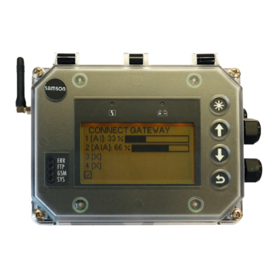
Operation 6 Operation Error LED SPS/battery warning LED Capacitive keys Status LEDs for GSM module Display Fig. 6-1: Operating controls of the SAM Connect Gateway 6.1 Capacitive keys The capacitive keys for on-site operation are located to the right of the display. Confirm, select, change Scroll upward, increase value Scroll downward, reduce value Back EB 9510 EN... -
Page 38: Display
Operation 6.2 Display As soon as the supply voltage is connected, an overview of option modules is shown on first start-up or, in all other cases, the start screen (see Fig. 6-2). Press key (in start screen) to go to the main menu. Settings can be made and process val- ues read in the main menu. The 'Start-up' section contains a description of the basic start-up settings. A list of parameters for on-site operation is included in Annex A (configuration in- structions). -
Page 39: Start-Up And Configuration
Start-up and configuration 7 Start-up and configuration The work described in this section is only to be performed by personnel appropriately quali- fied to carry out such tasks. Once the mounting and start-up activities have been completed, you can start with the set- tings. The gateway is ready for operation as soon as the supply voltage is connected. First start-up When the gateway is started up for the first time after delivery, an overview of the option modules appears on the display after connecting the supply voltage. The option module wiz-... -
Page 40: Settings
Start-up and configuration Note − Select ESC to exit the option module wizard at any time. − Select forward (>) and back (<) to navigate between steps. − The option module wizard can be started from the Device settings (2) menu/Option mod- ules (2.2)/Overview of option modules (2.2.1 and 2.2.1.1) by selecting a slot/option module ('Specialist' user level only). -
Page 41: Setting The Language
Start-up and configuration 7.1.2 Setting the language The following languages are available for selection in the language menu of the gateway: − English · German · French · Italian · Spanish The language can only be changed in the Specialist user level. 1. Press key (in start screen) to go to the main menu. 2. -
Page 42: Setting The Local Power Line Frequency
Start-up and configuration 7.1.4 Setting the local power line frequency The local power line frequency must be entered to be able to properly filter out any distur- bances which are transmitted over ground wires or external power supply units. The default power line frequency is 50 Hz. The power line frequency can only be changed in the Specialist user level. 1. Press key (in start screen) to go to the main menu. 2. Select Start-up (1) with key and confirm with key. -
Page 43: Operation
GSM module is installed. Aligning the antenna Move the antenna to the upright position for To use remote data transmission, SAMSON the best reception results. If a weather guard creates a user account for each customer in... - Page 44 Operation Table 8-1: LEDs and their meaning Color Illuminated Blinks Error or failure 2x: GSM module without SIM card 3x: incorrect PIN Green Fast blinking: data transmission in progress Green Searching for a network 1x: GSM connection OK 2x: server connection OK 3x: PIN code failed 4x: hardware error Fast blinking: incoming SMS text message Green 1x: system ON Table 8-2: Signal strength reading Reading CSQ value Signal quality 1) Red LED...
-
Page 45: Malfunctions
Malfunctions 9 Malfunctions Table 9-1: Icon showing status classification Status The work described in this section is only to Priority Meaning icon be performed by personnel appropriately Failure: the gateway can- qualified to carry out such tasks. not perform its task due to a malfunction. DANGER Out of specification: the Risk of fatal injury due to electric shock... - Page 46 Possible causes and recommended action Memory error (calibration) Memory error (data) The gateway has an internal device error. Î Contact SAMSON's After-sales Service. No factory calibration Internal data processing error Temperature inside device below min. The temperature limit inside the device has fallen limit below the adjusted min.
-
Page 47: Servicing
− Current firmware version connection of the power supply. − Required firmware version 10.2 Periodic inspection and Note The gateway was checked by SAMSON testing of the gateway before it left the factory. We recommend inspection and testing ac- Î The product warranty becomes void if cording to Table 10-1 at the minimum. - Page 48 Action to be taken in the event of a negative re- sult Check the markings, labels and nameplates on Contact SAMSON when nameplates or labels are the gateway for their readability and complete- damaged, missing or incorrect to renew them.
-
Page 49: Decommissioning
Decommissioning 11 Decommissioning The work described in this section is only to be performed by personnel appropriately qualified to carry out such tasks. DANGER Risk of fatal injury due to electric shock (230 V version). Î Before connecting wiring, performing any work on the device or opening the device, disconnect the voltage supply and protect it against unintentional re- connection. - Page 50 11-2 EB 9511 EN...
-
Page 51: Removal
Removal 12 Removal 12.2 Removing the gateway The work described in this section is only to 1. Put the gateway out of operation (see the be performed by personnel appropriately 'Decommissioning' section). qualified to carry out such tasks. 2. Removing the option module 3. Disconnect the wires for the power sup- NOTICE ply from the gateway. - Page 52 12-2 EB 9511 EN...
-
Page 53: Repairs
VBG 62 or similar regulations until they are handed over to the manufac- turer. Otherwise, SAMSON does not accept any responsibility. Defective gateways can be returned to SAMSON for repair. - Page 54 13-2 EB 9511 EN...
-
Page 55: Disposal
Disposal 14 Disposal We are registered with the Ger- man national register for waste electric equipment (stiftung ear) as a producer of electrical and electronic equipment, WEEE reg. no.: DE 62194439 Î Do not dispose of components, lubricants and hazardous substances together with your other household waste. Î Check whether a battery is inserted in the gateway and remove it before dis- posing of the device. - Page 56 14-2 EB 9511 EN...
-
Page 57: Certificates
Certificates 15 Certificates The following certificates are included on the next pages: − EU declaration of conformity for Type 5007 The certificates shown were up to date at the time of publishing. The latest certificates can be found on our website: u www.samsongroup.com > Products & Applications > Product selector > Automation Systems > SAM Connect Gateway (5007-2) EB 9511 EN 15-1... - Page 58 Management par la qualité totale Development Valve Attachments and Measurement Technologies SAMSON AKTIENGESELLSCHAFT · Weismüllerstraße 3 · D 60314 Frankfurt am Main Revision 09 Fon: +49 69 4009-0 · Fax: +49 69 4009-1507 · E-Mail: samson@samsongroup.com · Internet: www.samsongroup.com 15-2 EB 9511 EN...
-
Page 59: Annex A (Configuration Instructions)
Annex A (configuration instructions) 16 Annex A (configuration instructions) The menu structure and parameters for on-site operation are described below. Further set- tings can also be made in the TROVIS-VIEW software. These settings are described in the Operating Instructions (SAM Connect Gateway – Configuration with TROVIS-VIEW) u EB 9511-2. Note The availability of executed menu items and parameters depends on the version and configu- ration of the gateway as well as the option modules used. - Page 60 Annex A (configuration instructions) Menu Adjustment range/values/description Device settings General Identifier 2.1.1 Enter a freely selectable name for the device (max. 15 charac- ters) ▪ Enter characters as required (default: CONNECT GATEWAY) LCD backlight 2.1.2 Activate or deactivate LCD backlight ▪ ON, OFF (default) LCD deactivation time 2.1.3 Activate/deactivate the deactivation time for the LCD backlight. ▪ ON, OFF (default) Deactivation time 2.1.4 Enter the time after which the LCD is to be automatically switched off.
- Page 61 Annex A (configuration instructions) Menu Adjustment range/values/description Option modules Overview of option mod- 2.2.1 ules 2.2.1.0 Overview of option modules in four slots as graph, starts op- tion module wizard Slot 1 2.2.2 Slot 2 2.2.3 The available parameters of inserted options modules are listed depending on the optional additional function.
- Page 62 Annex A (configuration instructions) Menu Adjustment range/values/description Event: Broken cable ..10 Activates or deactivates the event for a detected cable break- age at the input of the AI option module. The event is activated when the signal falls below the switching threshold of 0.2 mA. ▪ ON (default), OFF Event: Residual current ..11 Activates or deactivates the event for a detected residual cur- rent violation at the input of the AI option module.
- Page 63 Annex A (configuration instructions) Menu Adjustment range/values/description Limit 3 ..20 Activate/deactivate limit 3 ▪ ON (default), OFF Mode ..21 An upper limit can be determined with 'Max. contact' and a lower limit with 'Min. contact' for limit 3. ▪ Max. contact, Min. contact (default) Limit ..22 Setting of limit 3 (depends on selected unit) ▪ 0.0 to 100.0 (default: 90.0) Parameter only shown when 'Signal source' = 'Pressure' or 'Temperature'.
- Page 64 Annex A (configuration instructions) Menu Adjustment range/values/description Zero point ..29 The zero correction allows the input value to be corrected by ±10 % at the maximum. The zero correction is always per- formed before the span correction. The following functions are available: – Set zero: zero is set to the current input value (e.g. 3 %) and the measured value is set to 0 %. – Reset zero: zero is set to 0 %. ▪ Set zero (default), reset zero The following values are displayed: – Measured value (analog input signal) in % – Currently adjusted zero – Measured value (analog input signal) in mA Span ...
- Page 65 Annex A (configuration instructions) Menu Adjustment range/values/description Explosion protection certi- 2.3.8 Indicates whether the SAM Connect Gateway has explosion fication protection approval ▪ No (the SAM Connect Gateway does not have any explosion protection certificates). Process data Temperature inside device Read the current device temperature in °C Heating Indicates the state of the heating (on/off) Battery voltage Battery voltage reading in V Diagnostics Status messages Status messages provide an overview on the current states of individual functions or components of the gateway. A corre- sponding status icon is assigned to failures and error messages: Failure (error class E1) Out of specification (error class E2)
- Page 66 Annex A (configuration instructions) Menu Adjustment range/values/description Operation duration 4.2.1 Reading of the entire operating time of the device (dd:hh:m- m:ss) Temperature events Max. temperature limit 4.3.1 Activate/deactivate the temperature monitoring with limit for max. temperature inside the device ▪ ON, OFF (default) Limit 4.3.2 Set an upper temperature limit within the specified range: if the current device temperature is above the adjusted limit, an error message is generated and displayed. The status changes to 'Out of specification'.
-
Page 67: Annex B
Contact our after-sales service for support concerning service or repair work or when malfunctions or defects arise. You can reach our after-sales service at aftersalesservice@samsongroup.com. Addresses of SAMSON AG and its subsid- iaries The addresses of SAMSON AG, its subsid- iaries, representatives and service facilities worldwide can be found on our website (www.samsongroup.com) or in all SAMSON... - Page 68 17-2 EB 9511 EN...
- Page 70 EB 9511 EN...
- Page 71 EB 9511 EN...
- Page 72 EB 9511 EN SAMSON AKTIENGESELLSCHAFT Weismüllerstraße 3 · 60314 Frankfurt am Main, Germany Phone: +49 69 4009-0 · Fax: +49 69 4009-1507 samson@samsongroup.com · www.samsongroup.com...
Need help?
Do you have a question about the 5007-2 Series and is the answer not in the manual?
Questions and answers