Table of Contents
Advertisement
Quick Links
Advertisement
Table of Contents

Related Manuals for FAMOCO FX915SC-ASK

Summary of Contents for FAMOCO FX915SC-ASK
- Page 1 User Manual FX915SC-ASK NFC Android Validator...
-
Page 2: Table Of Contents
How to install the front casing ................27 8.2.5 Troubleshooting & Maintenance ................27 How to clean plastic surfaces ..................28 How to store FX915SC-ASK ..................28 How to switch the device ON or OFF ................29 Home screen and synchronization ................29 How to read an NFC card ...................30 How to read a barcode (1D/2D) ..................31... - Page 3 13.2 NFC module information .....................37...
-
Page 4: Copyright
4 Limitation of liability Famoco shall not be liable for any loss of profits or indirect, special, incidental, or consequential damages resulting from or arising out of or in connection with using this product, whether or not Famoco had been advised, knew, or should have known the possibility of such damages. -
Page 5: About This Manual
5 About this manual Congratulations on becoming the owner of a Famoco FX9 validator. This user manual is specially designed to detail the device’s main functions and features. Please read this manual before using the device to ensure safe and correct use. -
Page 6: Accessories
Third-party accessories may not be compatible with your device. ● 7.1 AC adapter For Europe, Famoco is proposing as an accessory an AC adapter that allows the product to be powered from an AC plug. 7.2 Battery The product comes by default without a battery. In specific cases of use or environment, it may be necessary to install the battery. -
Page 7: Getting Started
8 Getting started 8.1 Product Content All Famoco FX9 validators are made of two parts: • A Back Casing (Wall or Pole) consisting of a system of attachment, a voltage-reducing card and USB ports. • A Front Casing containing all the intelligence of the device. -
Page 8: How To Install Back Casings Wall
Input voltage of 24V DC: Copper section mm2 24V DC (25 W/h, I=1,042,08) Cable length (m) minimum maximum Rigid wire’s (both ways) (PT 5%) (PT 2.5%) cross-section AWG equivalence 0.01 0.03 0,5 mm2 AWG 20 0.03 0.06 0,5 mm2 AWG 20 0.07 0.15 0,5 mm2... - Page 9 8.2.2.2 Prerequisite installation 8.2.2.2.1 Installation surface To ensure proper installation and sealing at the rear of the unit, the installation surface must be straight and level. A seal is still provided to compensate for roughness and surface defects. 8.2.2.2.2 Electrical recommendations Please refer to section 8.2.1 Electrical recommendations.
- Page 10 1. To ensure the tightness of the device, the breakable openings are available both for fixing and for the passage of cables. Identify and break only those that will be required for fixation among those available. 2. Use the drilling template, or directly mark the surface, to identify the position of the different holes to make to fix the support.
- Page 11 Cables can be routed directly from the rear of the unit, in the case of a hollow wall, or through the bottom of the cable gland. In both cases, the breakable or pierceable openings are available. 8.2.2.3 Assembly & electric installation 8.2.2.3.1 Mounting preparation In detail, the back of the validator in wall mounting consists of: ●...
- Page 12 8.2.2.3.2 Preparation of the back casing 1. Once the fixing holes and cable ducts have been identified and opened on the rear face, proceed to pass the cables and fix the back casing against the surface. The back casing is supplied with a seal which makes it possible to seal in the event of irregularities on the surface, make sure to place it during the installation.
- Page 13 For FX925SC-ING & FX925SF-ING, the jumper must be plugged. ii. For FX915SC-ASK & FX925SC-TT, the jumper must be removed. d. In the case of cables passing through protruding grommets, use the lower bracket to tighten and secure the cables against possible tearing.
- Page 14 5. For the installation of the intermediate part and the closing of the rear face, use the 8 screws supplied and the Torx screwdriver TT20, with rod length of 80 mm minimum to go to the bottom of the barrel, in order to screw and close the wall mount. 6.
-
Page 15: How To Install A Back Casing Pole
● VCC +5V DC must be lowered and stabilized in 5V DC ● VCC +12V/24V: o Must be 0V for FX915SC-ASK and FX925SC-TT as the jumper must have been removed during the installation. o Must be 12V or 24V (depending on the voltage used to power the FX9) for FX925SC-ING and FX925SF-ING. - Page 16 8.2.3.2.2 List of supplies Designation Commentaries Quantity 5.5 mm drill bit Drilling for the anti-rotation screw Drill bit between 12 and 16 mm Central hole drilling Tapered reamer, diameter of 20 Central hole drilling 1, optional Electrical cables 2 rigid-conductor power cables, cross-section and length depending on the vehicle layout (*).
- Page 17 8.2.3.3.4 Standard drilling template Place the unit at the desired height from the floor. Take care to check the specific height instructions for each use case. The standard drilling template is as follows: 1. Use the drilling template to identify the position and the different holes to be drilled on the pole to fix the support.
- Page 18 8.2.3.3.5 Drilling template for data cabling In case of data cables (USB) should arrive at the rear casing, and extra drilling holes on the pole could be considered. 8.2.3.4 Mechanical assembly & electrical installation Warning: For safety reasons, make sure that the power supply is turned off throughout the operation.
- Page 19 The installation of the validator uses the following elements: • 4 metal brackets, all identical • 2 anti-rotation screws with washers • screws for fixing the fixing brackets to the back casing • 16 plastic spacers (8 spacers per pair of fixing brackets) •...
- Page 20 2. For a perfect centering on the pole, place the recommended number of spacers for the diameter of the pole, then fix the lower bracket with the 4 flat-headed screws, as shown: In this example, only one spacer is placed behind the bracket. This configuration is suitable for 35 mm diameter bars.
- Page 21 ● Seal Type 3 can be identified by a “36 - 40” engraving 4. The fully assembled back casing will hold the rear seal halves and the rear brackets, as follows: 8.2.3.4.3 Mounting the back casing 1. Place the back casing on the pole, align the holes with the mounting brackets.
- Page 22 2. Stack the recommended number of spacers fixing screws, depending on the diameter of the pole, so that they serve as a stop against excessive tightening of the fixing bracket. Place the nuts/screws with the washers provided. 3. Place the upper brackets so that they align the hole(s) in the bar with the anti- rotation screw(s).
- Page 23 4. Tighten the self-locking nuts and the anti-rotation screw(s) using the pipe wrench. The result is: 8.2.3.4.4 Intermediate part fixing 1. Remove the lid that protects the access to the accessible electric items: the terminal block, the fuse and a jumper.
- Page 24 2. Pass the power cable through the opening in the center. 3. Place the remaining halves of the seals on the top and bottom of the intermediate part.
- Page 25 4. Use the 8 screws provided with the TT20 Torx-type screwdriver, with a minimum shank length of 80mm to go to the bottom of the clearance hole, to screw and fix the intermediate part on the rear casing. 5. Once both parts are fixed, let the power cable hang slightly while waiting for the wire connection.
- Page 26 3. Ensure the jumper is on the right configuration depending on the FX9 version you use: a. For FX925SC-ING & FX925SF-ING, the jumper must be plugged. b. For FX915SC-ASK & FX925SC-TT, the jumper must be removed. Finally, replace the lid, as shown in the image below, to hide the wiring and protect the access to...
- Page 27 8.2.3.5 External Peripherals & data cabling 8.2.3.5.1 External peripherals The back casing provides 2 female USB type A connectors for external peripherals and dongles. These peripherals will operate together with the front casing, once the FX9 validator is assembled. Please note the USB standard is USB 2.0. Therefore, the maximum power supply available per connector is 500 mA.
-
Page 28: How To Install The Front Casing
8.2.3.6 End of installation test Please refer to section 8.2.2.4 End of installation test. 8.2.4 How to install the front casing The installation of the front casing for wall and pole is the same, and it is done by fitting and then sliding it down. -
Page 29: How To Clean Plastic Surfaces
If the problem persists, contact the Famoco support team: support@famoco.com 8.3 How to clean plastic surfaces Here are a few extra tips to help keep you healthy and connected using your Famoco devices: ● Famoco devices without a protective case or screen protector: Spray an alcohol-based (70% isopropyl) directly on a soft lint-free cloth and wipe down your Famoco device while it is powered down and unplugged. -
Page 30: How To Switch The Device On Or Off
8.5 How to switch the device ON or OFF The product starts automatically as soon as it is powered on. 8.6 Home screen and synchronization Once your device is switched on it will start synchronizing. If there are no applications installed on it yet, the device will be locked on a screen as shown below Figure: No applications installed screen Connection... -
Page 31: How To Read An Nfc Card
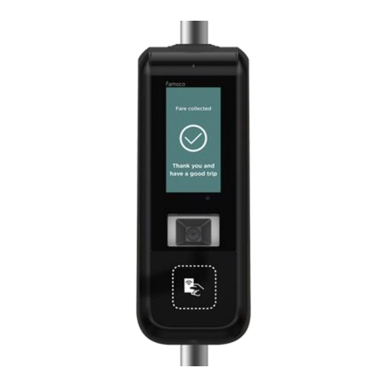
If the synchronization is in progress, please wait until it is complete. If the synchronization is complete but no applications have been installed, or if the synchronization has been aborted, please contact your customer support. 8.7 How to read an NFC card To read an NFC card, bring the card near the NFC design of a hand holding a card on the front casing, below the scan engine. -
Page 32: How To Read A Barcode (1D/2D)
8.8 How to read a barcode (1D/2D) To read a barcode (either from a mobile phone screen or a paper), place the barcode in front of the scan engine of the FX9 validator. Barcodes supported* 1D: UPC, EAN, Code 128, Code 39, Code 93, Code 11, Matrix 2 of 5, Codabar Interleaved 2 of 5, Mis Plessey, GSI DataBar, China Postal, Korean Postal, etc. -
Page 33: Technical Specifications
Technical specifications MTK6739WW, Quad-core, Cortex (1.5GHz) Processor PowerVR GE8100 Famoco OS based on Android 8.1 Memory Mass Storage 16GB Expansion Slot Micro SD up to 32GB Characteristics 5.0”, IPS FWVGA 960x480 pixels Display 5.0” touchscreen Touch Panel Notification 1 multi-color LED (red, green, blue) - Page 34 ● ITSO, Calypso®, VDV KA ● CTS512B, CTM512B, ST SR Family ● Sony Felica® ● Java Card® Dual 3FF + 2FF 850/900/1800/1900 MHz 850/900/1900/2100 MHz FDD:700/800/850/900/1800/2100/2600 MHz TDD: 2300/2500/2600MHz Connectivity Wi-Fi Dual band (2.4GHz and 5GHz) 802.11 a/b/g/n Bluetooth 4.2, BLE Camera Front camera 5MP FF IC...
-
Page 35: Warranty Information
Operating -5°C to 50°C / 23°F to 122°F Temperature Storage FX915SC-ASK -10°C to 60°C / 14°F to 140°F Temperature without battery Humidity Operating 10% to 90% (non-condensed) Storage 5% to 95% Charging: 0°C to 55°C / Operating Temperature Discharging: -10°C to 60°C /... -
Page 36: Declaration Of Conformity
For disposal in countries outside of the European Union, this symbol is only valid in the ● European Union (EU). If you wish to discard this product, please contact your local authorities or dealer and ask for the correct method of disposal. 12 Declaration of Conformity You can find the Declaration of Conformity here: https://www.famoco.com/conformity/... -
Page 37: Band And Power
13 Band and power 13.1 Support band information and power FX915SC-ASK radio equipment operates with the following frequency bands and maximum radio- frequency power: Supported Type Power(dBm) frequency bands 1800 1900 1900 2100 BAND 1 BAND 3 BAND 5 BAND 7... - Page 38 BAND 40 BAND 41 WIFI 2.4G 18±1 19±1 5±1 5±1 13.2 NFC module information Working frequency: 13.56MHZ Sensing distance: EUT is designed to maintain a distance of 4 cm with the user.
- Page 39 April 2021...
Need help?
Do you have a question about the FX915SC-ASK and is the answer not in the manual?
Questions and answers