Table of Contents

Related Manuals for Apator Metra E-RM 30

Summary of Contents for Apator Metra E-RM 30
- Page 1 LECTRONIC RADIO MODULE FOR WATER METER E-RM 30 Installation and service manual APATOR METRA s.r.o. Havlíčkova 919/24 787 64 Šumperk tel.: +420 583 718 111 fax: +420 583 718 150 e-mail: prodej@metra - su.cz www: http://www.metra - su.cz...
-
Page 2: Table Of Contents
5. W ....................8 ORK WITH A RADIO MODULE 5.1. Installation E-RM 30 to the water meter....................8 5.2. Reading data, defining parameters and operating modes..............8 5.3. Change of operation mode........................8 5.3.1. Switch a radio module to the working mode..................9 5.3.2. -
Page 3: Introduction
E-RM 30 rod antenna features a very good efficiency. Deu to this high-quality signla it is possible to read data without entering the building eve in case of installation in the shaft of multiplestorey building. Data reading can be made by billing company employee using mobile receiving unit. -
Page 4: Description
5.3. Change of operation mode). Some models of the E-RM 30 (e.g. chapter 2.1. Type list) are able to detect attempts to manipulate the water meter by using an external magnetic field (for example by using a magnet). The actual transfer of data between the water meter and the radio module is based on an optical principle (just like the radio module itself) and is therefore not affected by a magnetic field. -
Page 5: Construction And Technical Data
– records the data of any manipulation or removal of device magnetic pole deletction (> 3 mT) – only E-RM 30.3** an option to mechanically lock the radio module to the water meter Backup data... -
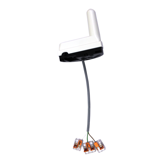
Page 6: Radio Module E-Rm 30 Construction
3.1.1. Radio module E-RM 30 construction The E-RM 30 unit consists of a top part with an aperture for infrared communication and a bottom part for detecting the water meter. Both parts provide a protective covering for the printed circuit boards, electronic components, antenna and battery. -
Page 7: Sleeping Mode
We recommend to do an activation by 5 liters flow immediately after the installation. Otherwise radio module E-RM 30 is not sending any data and it is not possible to chcek radio modules availability and functionallity with radio reading unit. -
Page 8: Work With A Radio Module
1. Check the condition of the intended water meatier and its housing. If there is any damage or contamination, clean or replace the meter. 2. Remove the cardboard plugs which are used to protect the E-RM 30 radio module's sensors during transport. Retain the plugs for covering the sensors during any modes changes (5.3 Change of operation mode). -
Page 9: Switch A Radio Module To The Working Mode
3. Readiness of the IRU10.00 is indicated by -PrE-. Place the readout head onto the infrared viewing port of the E-RM 30 and press the button briefly. Ongoing communication is indicated by IP on the viewing screen. 4. A successful mode change is indicated by a single beep and the display showing o. Pro . -
Page 10: Switch A Radio Module To The Sleeping Mode
--A--. 3. Readiness of the IRU10.00 is indicated by -PrE-. Place the readout head onto the infrared viewing port of the E-RM 30 and press the button briefly. Ongoing communication is indicated by IP on the viewing screen. 4. A successful mode change is indicated by a single beep and the display showing o. uPr. -
Page 11: Application And Disposal
• method of transport • Order example 100 pcs E-RM 30, required delivery 28.2.2012, EXW + filled Setting protocol. 7.2. P ACKING Packing sheet is included in every box (e.g. Illustracion 3: Packing sheet) with mark of producer, device type, number of items and their serial numbers, packing date and the name of operative who checked and packed the products. - Page 12 E-RM 30 Installation and service manual M2016/09f[EN] Illustracion 3: Packing sheet 12 / 17...
-
Page 13: Water Meters
E-RM 30 Installation and service manual M2016/09f[EN] 8. W ATER METERS 8.1. C HOOSING THE RIGHT WATER METER SIZE The main criterior for choosing the right water meter size (nominal diameter) should always be the water meter working conditions, that is the average and maximum value of a passing water working flow. -
Page 14: Structure
E-RM 30 Installation and service manual M2016/09f[EN] 8.2.3. Structure hermetic counter squeeze- resistant counter mechanism with blockade against multiple rotating triple – antimagnetic protection anti – freeze panel double – sided bearing axle intel strainer Illustration 4: Water meter structure 8.2.4. Testing at the receipt The water meter supplied should be checked for possible external damage which occurred during transport, especially the body and threaded connectors and the counter cover. - Page 15 E-RM 30 Installation and service manual M2016/09f[EN] the water meter well and additionally the water meter and its equipment should be installed far enough from the well bottom. 2. In the location of installation, the water meter connot be at risk of being hit or be subjected to vibrations caused by other devices in the vicinity or subjected to high ambient air temperature, contamination, flooding and corrosive action of the surroumdings.
-
Page 16: Filling With Water And Start - Up Of Flow Transducers
E-RM 30 Installation and service manual M2016/09f[EN] 1 – horizontal orientation (class B: R100 – H) 2,3 – diagonal orientation (class A: R40 to 63 – V) 4,5,6 – vertical orientation (class A: R40 to 63 - V) Ilustration 6: Sample permitted installation positions 9. -
Page 17: Water Meter Marking (Example)
E-RM 30 Installation and service manual M2016/09f[EN] 8.2.7. Water meter marking (example) type temperature class continuous flow volume alternative connector JS 90 – 2,5 – G1 8.3. W GSD8-RF ATER METER Nominal flow Q 1,5 m Maximal flow Q Max. working pressure...
Need help?
Do you have a question about the E-RM 30 and is the answer not in the manual?
Questions and answers