
Related Manuals for Moeller SmartWire SWIRE-GW-DP


Summary of Contents for Moeller SmartWire SWIRE-GW-DP
- Page 1 Connection System SmartWire SWIRE-GW-DP Hardware and Function Description 11/06 AWB1251-1590GB W e keep power under control.
- Page 2 No part of this manual may be reproduced in any form (printed, photocopy, microfilm or any other process) or processed, duplicated or distributed by means of electronic systems without written permission of Moeller GmbH, Bonn. Subject to alteration without notice.
- Page 3 Warning! Dangerous electrical voltage! Before commencing the installation • Disconnect the power supply of the device. • Suitable safety hardware and software measures should be implemented for the • Ensure that devices cannot be accidentally I/O interface so that a line or wire breakage restarted.
- Page 4 • Measures should be taken to ensure the • Wherever faults in the automation system proper restart of programs interrupted may cause damage to persons or property, after a voltage dip or failure. This should external measures must be implemented to not cause dangerous operating states even ensure a safe operating state in the event for a short time.
-
Page 5: Table Of Contents
11/06 AWB1251-1590GB Contents About this manual Intended users Additional device manuals Reading convention About the PROFIBUS-DP gateway SWIRE-GW-DP System overview Design of the SWIRE-GW-DP Description of function Installation Set PROFIBUS-DP station address Connect SmartWire connection cable Connect supply voltages Connect PROFIBUS-DP Connection assignment PROFIBUS-DP Terminating resistors EMC-conformant wiring of the network... - Page 6 11/06 AWB1251-1590GB Contents PROFIBUS-DP functions Configuration of the DP master Slave modules – Universal module – SWIRE-DIL module – SWIRE-4DI-2DO-R module Diagnostic data – Diagnostics information format – Meaning of the diagnostics information GSD file Fault-finding Appendix Technical Data – General –...
-
Page 7: About This Manual
• Connection system SmartWire, modules AWB1210+1251-1591, • Connection system SmartWire, EASY223-SWIRE AWB2528+1251-1589. The manuals are available for download on the Internet as PDF files. They can be quickly located at http://www.moeller.net/en/support by entering the document number as the search term. -
Page 8: Reading Convention
11/06 AWB1251-1590GB About this manual Reading convention Symbols used in this manual have the following meanings: Indicates instructions to be followed. Attention! Warns of the risk of material damage. Caution! Warns of the possibility of serious damage and slight injury. Warning! Indicates the risk of major damage to property, or serious or fatal injury. -
Page 9: About The Profibus-Dp Gateway Swire-Gw-Dp
11/06 AWB1251-1590GB About the PROFIBUS-DP gateway SWIRE-GW-DP The communication module SWIRE-GW-DP has been developed for automation tasks with the PROFIBUS-DP fieldbus. The SWIRE-GW-DP is a gateway and can only be operated in conjunction with the SmartWire system. The PROFIBUS-DP gateway always operates with a modular DP slave in the PROFIBUS-DP network. -
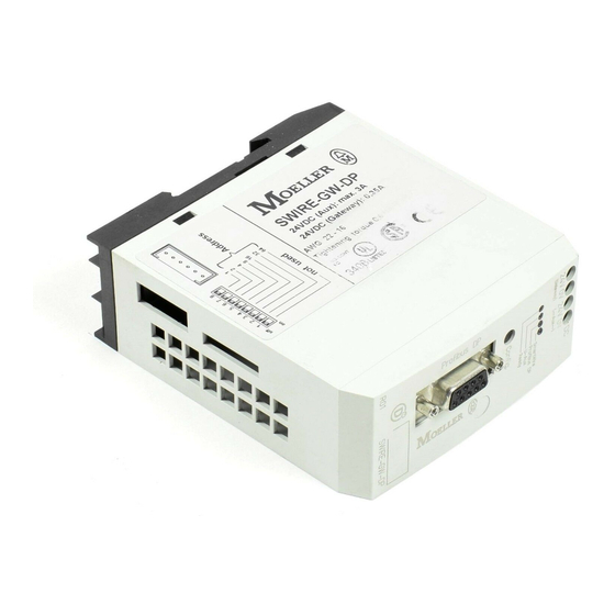
Page 10: Design Of The Swire-Gw-Dp
11/06 AWB1251-1590GB About the PROFIBUS-DP gateway SWIRE-GW-DP Design of the SWIRE-GW-DP Figure 2: Device view a Connection to PROFIBUS_DP, 9-pole SUB-D socket, a page 12 b Configuration button, a page 19 c 4 green status LEDs, a page 20 d Gateway power supply terminal, a page 11 e Contactor coil (aux.) power supply terminal, a page 11 f Socket Out for SmartWire connection cable, a page 10 g DIP switch for the address setting of the PROFIBUS-DP module,... - Page 11 11/06 AWB1251-1590GB Description of function • SmartWire module for DILM Figure 3: SWIRE-DIL – Contactor switching state feedback and PKZM0 switching state feedback (Read, as viewed from the PROFIBUS-DP master) – Contactor control ON/OFF (Write, as viewed for PROFIBUS-DP master) •...
- Page 12 11/06 AWB1251-1590GB...
-
Page 13: Installation
11/06 AWB1251-1590GB Installation Set PROFIBUS-DP station Every PROFIBUS-DP slave requires its own unique address in address the PROFIBUS-DP network. The PROFIBUS-DP address in the SWIRE-GW-DP is set using 7 DIP switches 2 to 8 in binary format. DIP switch 1 is not assigned with a function. -
Page 14: Connect Smartwire Connection Cable
11/06 AWB1251-1590GB Installation 2 3 4 5 6 7 8 not used Figure 7: Setting of the slave address Connect SmartWire The slaves in the SmartWire system are connected unsing 6- connection cable pole connection cables available in different lengths (a AWB1210+1251-1591GB). -
Page 15: Connect Supply Voltages
11/06 AWB1251-1590GB Connect supply voltages Connect supply voltages The gateway SWIRE-GW-DP is operated with a 24 V DC supply voltage (a chapter “Technical Data”, page 35). An additional 24 V DC control voltage is provided for the contactor coils. Connect the SWIRE-GW-DP via the connection terminals 24 V and 0 V to the 24 V DC power supply. -
Page 16: Connect Profibus-Dp
(protective extra low voltage). Connect PROFIBUS-DP The SWIRE-GW-DP is connected to the PROFIBUS-DP fieldbus with a special PROFIBUS-DP cable from the Moeller accessory range. Connect the 9-pole SUB D connector of the PROFIBUS-DP cable to the SUB D connector. -
Page 17: Connection Assignment Profibus-Dp
11/06 AWB1251-1590GB Connection assignment PROFIBUS-DP Connection assignment PROFIBUS-DP CNTR-P RxD/TxD-P (B/B') RxD/TxD-N (A/A') DGND Signal name Designation not used – not used – RxD/TxD-P Receive/Send data P (B line) CNTR-P/RTS Request to Send DGND Data ground +5 V DC for external bus termination not used –... -
Page 18: Terminating Resistors
SUB D connector. The PROFIBUS-DP data plug from Moeller allows switching on and off both termination resistors. EMC-conformant wiring of Undesired faults can occur on the fieldbus due to the network electromagnetic interference. -
Page 19: Potential Separations
11/06 AWB1251-1590GB Potential separations for top-hat rail for mounting plate ZB4-102-KS1 ZB4-102-KS1 KLBü 3-8 SC FM 4/TS 35 (Weidmüller) (Weidmüller) Figure 10: Shielding of network cable Potential separations The following electrical isolation measures apply for the SWIRE-GW-DP interfaces: • Potential isolation of the PROFIBUS-DP to the supply voltage and to the SmartWire system, •... -
Page 20: Data Transfer Rates - Automatic Baud Rate Detection16
11/06 AWB1251-1590GB Installation Data transfer rates – After switch on the gateway SWIRE-GW-DP automatically automatic baud rate detects the baud rate used in the PROFIBUS-DP network. detection However, at least one slave in the network must transfer data in order for the detection to be possible. The following baud rates are supported: •... - Page 21 11/06 AWB1251-1590GB Maximum distances/bus cable lengths Distance between two slaves if cable type A to IEC 61158 is used. Table 2: Cable type A Baud rate Max. cable length [kBit/s] Cable type A 1200 19.2 1200 93.75 1200 187.5 1000 1500 3000 6000...
- Page 22 11/06 AWB1251-1590GB...
-
Page 23: Commissioning
11/06 AWB1251-1590GB Commissioning Before switching on the supply voltage for the gateway ensure that the contactor coils, the bus connection and the SmartWire system are correctly connected. Initial switch on Verify that the DIP switch of the PROFIBUS-DP address of the gateway is set, a page 9. -
Page 24: Meaning Of The Status Leds
11/06 AWB1251-1590GB Commissioning there are any divergences they are indicated by a slowly flashing SmartWire LED (a section “Diagnostic data”, page 26). Switch in the PROFIBUS-DP fieldbus. As soon as the gateway is integrated into the PROFIBUS- DP network the BUS LED will light up permanently. Valid data will only be sent via the PROFIBUS-DP to the gateway once the PROFIBUS LED stays permanently ON. -
Page 25: Smartwire Led
11/06 AWB1251-1590GB Meaning of the status LEDs SmartWire LED Continuous SmartWire system is ok light No supply voltage available on the PROFIBUS-DP gateway Fast flashing Transmission error in the SmartWire system Slow flashing Error in the configuration of the SmartWire system, target and actual configuration do not match PROFIBUS LED Continuous... - Page 26 11/06 AWB1251-1590GB...
-
Page 27: Profibus-Dp Functions
32). • Motorola based CPU (e.g. for Siemens S7): – Moel4d12.gsd, – KM4D12_N.bmp, – KM4D12_D.bmp. • Intel based CPU (e.g. for Moeller XC100/200, PS4): – Moe4d12.gsd, – KM4D12_N.bmp, – KM4D12_D.bmp. Add the “SmartWire Gateway (S7/S5)” slave in the topology of the PROFIBUS segment to be configured. -
Page 28: Slave Modules
11/06 AWB1251-1590GB PROFIBUS-DP functions Slave modules The gateway SWIRE-GW-DP is a PROFIBUS-DP slave conform to IEC 61158. In the PROFIBUS-DP configurator of the master control the following modules of the “SmartWire Gateway” slave can be used when the corresponding GSD file is used: •... -
Page 29: Swire-4Di-2Do-R Module
11/06 AWB1251-1590GB Slave modules Table 6: Receive data (read from the point of view of the PROFIBUS-DP) SWIRE-DIL Contactor status PKZ status SWIRE-DIL status 1) a table 7. Table 7: Definition of the bit Contactor status PKZ status SWIRE-DIL status Error SWIRE-4DI-2DO-R module Table 8:... -
Page 30: Diagnostic Data
11/06 AWB1251-1590GB PROFIBUS-DP functions Table 10: Receive data (read from the point of view of the PROFIBUS-DP) SWIRE-4DI-2DO-R Status input I1 Status input I2 Status input I3 Status input I4 SWIRE-4DI-2DO-R status 1) a table 11. Table 11: Definition of the bit Status input SWIRE-4DI-2DO-R status Input 0... -
Page 31: Diagnostics Information Format
11/06 AWB1251-1590GB Diagnostic data Diagnostics information format Reading of the diagnostics is implemented directly via the DP diagnostics command or via the defined diagnostics byte of the PROFIBUS-DP master using the PROFIBUS-DP configuration. Observe the documentation of the master device here. At least 11 octets are read as diagnostics. - Page 32 11/06 AWB1251-1590GB PROFIBUS-DP functions Diagnosticsp Designation osition Octet 3 Bit 0…6 Not used Bit 7 Overflow of additional diagnostics information Octet 4 DP master station address Octets 5 and 6 Ident no. DP slave: 4D12 Octet 7 Length of additional diagnostics information Octet 8 Status Type: 130 Octet 9...
-
Page 33: Meaning Of The Diagnostics Information
11/06 AWB1251-1590GB Diagnostic data Diagnosticsp Designation osition Octet 14 Bit 0…1 Status SmartWire module 13 Bit 2…3 Status SmartWire module 14 Bit 4…5 Status SmartWire module 15 Bit 6…7 Status SmartWire module 16 Meaning of the diagnostics information The read diagnostics information has the following meaning: Table 13: Data content of the diagnostics information Designation Meaning... - Page 34 11/06 AWB1251-1590GB PROFIBUS-DP functions Designation Meaning Explanation/remedy Master already The SWIRE-GW-DP is occupied by another – present DP master. Not used Does not contain information to be – evaluated Parameterization The SWIRE-GW-DP waits for the Temporary state request parameterization telegram of the DP master.
- Page 35 11/06 AWB1251-1590GB Diagnostic data Designation Meaning Explanation/remedy Status Specifier The SWIRE-GW-DP provides no – “incoming/outgoing” signal for the sent diagnostics information (Status): 00 Status type The SWIRE-GW-DP uses the status type – “status message”: 01 Sync mode active The DP master has activated the Is not supported.
-
Page 36: Gsd File
The GSD file contains common PROFIBUS slave descriptions. Two different GSD files exist for the SmartWire system: • Motorola based CPU (e.g. for Siemens S7): Moel4d12.gsd, • Intel based CPU (e.g. for Moeller XC100/200, PS4): Moe4d12.gsd Two bitmaps are also available: • KM4D12_N.bmp, •... -
Page 37: Fault-Finding
11/06 AWB1251-1590GB Fault-finding Fault-finding In addition to the diagnostic messages in the PROFIBUS-DP (a section “Diagnostic data”, page 26) the LEDs on the SmartWire modules and on the PROFIBUS-DP gateway can be used to trace the fault. Table 15: Error messages Part Event Explanation... - Page 38 11/06 AWB1251-1590GB...
-
Page 39: Appendix
11/06 AWB1251-1590GB Appendix Technical Data General Standards and regulations General IEC/EN 60947, EN 55011, EN 55022 IEC/EN 61000-4, IEC/EN 60068-2-27 PROFIBUS-DP IEC 61158 Mounting Top-hat rail IEC/EN 60715 (35 mm) Dimensions (W x H x D) 35 x 90 x 109 Weight 0.15 Terminal capacity... -
Page 40: Environmental Conditions
11/06 AWB1251-1590GB Appendix Environmental conditions Ambient climatic conditions Ambient temperature Operation °C –25…+55 Storage °C –25…+70 Condensation Prevent condensation with suitable measures Relative humidity, non-condensing 5…95 (IEC/EN 60068-2-30) Air pressure (in operation) 795…1080 Ambient mechanical conditions Degree of protection (IEC/EN 60529) IP20 Pollution degree Mounting position... -
Page 41: Electromagnetic Compatibility (Emc)
11/06 AWB1251-1590GB Technical Data Electromagnetic compatibility (EMC) Electromagnetic compatibility (EMC) Electrostatic discharge (IEC/EN 61000-4-2, Level 3, ESD) Air discharge Contact discharge Electromagnetic fields (IEC/EN 61000-4-3, RFI) Radio interference suppression Class A (EN 55011, EN 55022) Burst Impulse (IEC/EN 61000-4-4, Level 3) Power cables Signal cables High-energy pulses (surge) -
Page 42: Power Supply Voltages
11/06 AWB1251-1590GB Appendix Power supply voltages Voltage supply, Gateway electronic and Smart-Wire station electronic Gateway Rated operating voltage U V DC 24, –15 %, +20 % Gateway Admissible range 20.4…28.8 Residual ripple Maximum current consumption at 350 (typically 110 gateway + typically 24 V DC 15 per SmartWire module) Voltage dips (IEC/EN 61131-2) -
Page 43: Led Displays
11/06 AWB1251-1590GB Technical Data LED displays LED displays Ready for operation Ready: green Power supply SmartWire contactors : green Status PROFIBUS-DP PROFIBUS-DP: green Status SmartWire SmartWire: green PROFIBUS-DP PROFIBUS-DP Connection types SUB-D 9 pole, socket Station address 1…125 Address allocation DIP switch Electrical isolation for supply voltage U... -
Page 44: Smartwire System
11/06 AWB1251-1590GB Appendix SmartWire system SmartWire Connection types Plug, 6-pole Data/power cable 6 core flat-band cable maximum cable length, SmartWire Max. 4 system Bus termination Station address Automatic assignment Station Max. 16 Address allocation None Electrical isolation for supply voltage U for supply voltage U Gateway... -
Page 45: Dimensions
11/06 AWB1251-1590GB Dimensions Dimensions 35.5... - Page 46 11/06 AWB1251-1590GB...
-
Page 47: Index
11/06 AWB1251-1590GB Index Baud rate ............16 Configuration ............20 Configuration button ........6, 19 Connect SmartWire connection cable ......10 Connection PROFIBUS-DP ..........12 Supply voltages ..........11 Connection cable SmartWire ............10 Diagnostics messages ..........26 DIP switch .............9 EMC measures ............14 Error messages ............33 GSD file ............23, 32 LEDs Error messages ..........33 Meaning ............20... - Page 48 11/06 AWB1251-1590GB Index Read ..............7 Set station address ..........9 Shielding, network cable ........15 Slave ..............5 Slave modules .............24 SmartWire Connection cable .........10 I/O module .............6 Module for DILM ..........6 Rung ..............6 Standards ............35 Station address .............9 Status LEDs ............20 SUB-D Plug .............12 Socket ............12 SWIRE-4DI-2DO-R...
- Page 49 © 2006 by Moeller GmbH Subject to alteration AWB1251-1590GB Doku/Doku/xxx 11/06 Moeller shows the way. For over 100 years. Our latest development is called Darwin Technology – the evolution in the control cabinet. A quantum leap in the merging of switching devices and automation. And thus a leap forward into the technology of the future.
Need help?
Do you have a question about the SmartWire SWIRE-GW-DP and is the answer not in the manual?
Questions and answers