Table of Contents
Advertisement
Quick Links
Advertisement
Table of Contents

Related Manuals for Hanwha Techwin Wisenet SMT-1030PV


Summary of Contents for Hanwha Techwin Wisenet SMT-1030PV
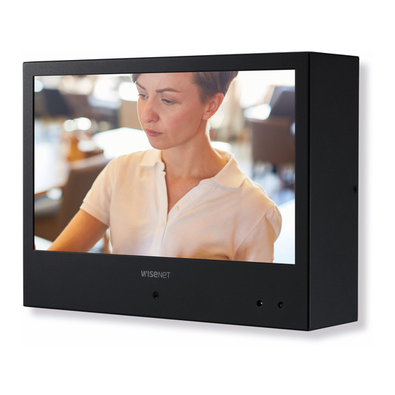
- Page 1 PUBLIC VIEW MONITOR SMT-1030PV SMT-2730PV SMT-3230PV...
- Page 2 SAFETY INSTRUCTIONS 1. WARNING To reduce the risk of fire or electric shock, do not expose this product to rain or moisture. Do not insert any metallic object through the ventilation grills or other openings on the equipment. Apparatus shall not be exposed to dripping or splashing and that no objects filled with liquids, such as vases, shall be placed on the apparatus.
-
Page 3: Table Of Contents
CONTENTS OVERVIEW Package Contents Names and functions of each part Remote control MENU SETTINGS OSD Menu setting Camera setup NETWORK CONNECTION AND SETUP & Connecting the PVM Directly to Local Area Networking WEBVIEWER Connecting the PVM Directly to a DHCP Based DSL/Cable Modem Using Device Manager Automatically searching camera... -
Page 4: Overview
overview overview PACKAGE CONTENTS Please check the following contents are included in addition to the main unit. Public View Monitor User Manual Warranty card Power Cable Adapter Remote Controller Battery Terminal Block Ferrite Core (SMT-1030PV only) 4_ overview... -
Page 5: Names And Functions Of Each Part
NAMES AND FUNCTIONS OF EACH PART SMT-1030PV(10") Front ➊ ➋ ➌ Name Description of functions ➊ Camera Lens TNB-6030 camera is installed. ➋ IR Receiver Receive IR signal from Remote Controller. Displays the power ON/OFF status. ➌ ON – GREEN OFF –... - Page 6 overview Back ➊ ➋ ➌ ➍ ➎ Name Description of functions ➊ DC 12V This is the power input terminal. ➋ ALARM ALARM signal input / output ➌ Micro SD Compartment for the Micro SD card. ➍ Power of Ethernet(802.3at) Resets the camera installed in the monitor to its factory default settings.
- Page 7 SMT-2730PV(27") / 3230PV(32") Front ➊ ➋ ➌ Name Description of functions ➊ Camera Lens TNB-6031 camera is installed. ➋ IR Receiver Receive IR signal from Remote Controller. Displays the power ON/OFF status. ➌ ON – GREEN OFF – RED English _7...
- Page 8 overview Back ➊ ➋ ➌ ➍ ➎ ➏ ➐ Name Description of functions ➊ HDMI HDMI input terminal. ➋ Connects the USB devices. ➌ DC 12V This is the power input terminal. ➍ ALARM ALARM signal input / output ➎ NETWORK Used to connect the Ethernet cable for network connection.
-
Page 9: Remote Control
REMOTE CONTROL POWER Turn ON / OFF the monitor COLOR TEMP HDMI Select color temperature of the screen Select HDMI mode (SMT-2730PV/SMT-3230PV only) HDMI2/CAMERA S.SET Select CAMERA mode Toggle source (HDMI/CAMERA) (SMT-2730PV/SMT-3230PV only) (SMT-2730PV/SMT-3230PV only) SCAN MODE Select the scan mode of the screen MENU/EXIT Activate and exit the OSD menu Those buttons without specific description are deprecated buttons. -
Page 10: Menu Settings
menu settings OSD MENU SETTING MENU STRUCTURE When user presses the menu key, the first “PICTURE” menu is displayed. Select by “◀” key then two types of menu functions are shown as below. • PICTURE ( ) : Menu related to PICTURE Function •... - Page 11 Picture Mode Picture Mode can select 4 modes as Mild, Dynamic, Standard and User as shown in the figure below. Press the "◀, ▶" key to change the mode. Picture Mode User Picture Mode Dynamic Picture Mode Standard Picture Mode Mild Contrast 50 Contrast 45...
- Page 12 menu settings Aspect Ratio Aspect Ratio allows user to select the each aspect ratio as shown in the figure below. (However, activated list is according to the input port and the input resolution.) Aspect Ratio Auto 4 : 3 16 : 9 Zoom 1 Zoom 2 Just Scan...
- Page 13 OPTION MENU The Option Menu can be selected from the following 7 modes by pressing the ▲ or ▼ key. functions Description OSD Language Selectable OSD Menu Language Blending Adjust blending for OSD Menu and Main window OSD Duration Setting Duration time of OSD Menu Restore Factory Default Resets the monitor to its factory default settings.
- Page 14 menu settings OSD Language As shown in the figure below, OSD Language can be selected by “▲, ▼” key. OSD Language English Espaol Franais Deutsch Italiano MENU Press the EXIT button to exit the Setup screen. Then, the language will be changed to the selected language.
- Page 15 Software Update(Monitor) Software update default can be selected by pressing the "MENU" key. Select Yes or No by the “◀, ▶” key. Are you sure? Software Update ◀ ▶ See below for more information on how to update software for each model: - SMT-1030PV: You can update it using a Micro SD card that can be inserted into the Micro SD card port inside the product.
-
Page 16: Camera Setup
menu settings CAMERA SETUP Supported video modes You can use various video modes, and some video modes need to be set up in the camera web viewer. Still image Live video Recording in Progress You can watch a live monitoring feed. You can see images with Still image. -
Page 17: Network Connection And Setup
network connection and setup & webviewer You can set up the network settings according to your network configurations. CONNECTING THE PVM DIRECTLY TO LOCAL AREA NETWORKING Connecting to the PVM from a local PC in the LAN 1. Launch an Internet browser on the local PC. 2. -
Page 18: Connecting The Pvm Directly To A Dhcp Based Dsl/Cable Modem
network connection and setup & webviewer CONNECTING THE PVM DIRECTLY TO A DHCP BASED DSL/CABLE MODEM INTERNET DSL/Cable Modem External Remote PC DDNS Server (Data Center, KOREA) 1. Connect the user PC directly with the PVM. 2. Run the Device Manager and change the IP address of the PVM so that you can use the web browser on your desktop to connect to the Internet. -
Page 19: Using Device Manager
USING DEVICE MANAGER Device manager program can be downloaded from <Technical Guides>-<Online Tool> menu at Hanwha Techwin website (http://www.hanwha-security.com). More instructions of Device Manager can be found at <Help> menu of the main page. AUTOMATICALLY SEARCHING CAMERA If a camera is connected to the same network of the PC where device manager is installed, you can find network camera by using search function. - Page 20 network connection and setup & webviewer If using a Broadband Router ~ IP Address : Enter an address falling in the IP range provided by the Broadband Router. ex) 192.168.1.2~254, 192.168.0.2~254, 192.168.XXX.2~254 ~ Subnet Mask : The <Subnet Mask> of the Broadband Router will be the <Subnet Mask>...
-
Page 21: Manually Registering Camera
Configuring Dynamic IP Receive IP address from DHCP ~ Example of the Dynamic IP environment - If a Broadband Router, with cameras connected, is assigned an IP address by the DHCP server - If connecting the camera directly to modem using the DHCP protocols - If IPs are assigned by the internal DHCP server via the LAN 1. -
Page 22: Automatically Configuring Ip
network connection and setup & webviewer AUTOMATICALLY CONFIGURING IP 1. Click the camera from the list that you want to automatically configure the IP. TNB-6030 2. Click < + > at the main page of device manager. ~ Equipment Setting menu appears. 3. - Page 23 Setting up Port Range Forward for several network cameras ~ You can set a rule of Port Forwarding on the Broadband Router device through its configuration web page. ~ A user can change each port using the camera setting screen. When Camera1 and Camera2 are connected to a router : ...
-
Page 24: Connecting To The Camera From A Shared Local Pc
network connection and setup & webviewer CONNECTING TO THE CAMERA FROM A SHARED LOCAL PC 1. Run device manager. It will scan for connected cameras and display them as a list. 2. Double-click a camera to access. The Internet browser starts and connects to the camera. Access to the camera can also be gained by typing the camera’s IP address in the address bar of the Internet browser. - Page 25 If the HTTP port is other than 80 1. Launch the Internet browser. Type the IP address and HTTP port number of the camera in the address bar. ex) IP address : 192.168.1.100:HTTP Port number(8080) ; http://192.168.1.100:8080 - the Login dialog should appear. Using URL 1.
-
Page 26: Password Setting
network connection and setup & webviewer PASSWORD SETTING When you access the product for the first time, you must register the login password. For a new password with 8 to 9 digits, you must use at least 3 of the following: uppercase/lowercase letters, numbers and special characters. -
Page 27: Setup Screen
setup screen SETUP On the network, you can set up basic information on the camera, video and audio, network, events, people counting, heatmap and system. 1. On the live screen, click the [Setup ( )] button. 2. The Setup screen appears. Recording in Progress CREATING A TEXT OVERLAY 1. -
Page 28: Setting Slide Show
setup screen SETTING SLIDE SHOW Setting Micro SD card ➌ 1. From the Setup menu, select the <Event> tab. ➊ 2. Click <Storage>. ➋ 3. Select <On> for the <Record> section of Micro SD Card, and click <Apply>. 4. Once Status of Micro SD Card is activated, click <Format>. ➍... - Page 29 Motion detection setup 1. From the Setup menu, select the <Event> tab. 2. Click <Event setup>. 3. Check the <Motion detection> box. - Clicking Motion detection moves you to the Motion detection menu setup screen. 4. Click <Apply>. Motion detection menu setup 1.
-
Page 30: Setting Alarm Input
setup screen SETTING ALARM INPUT Connecting to the I/O port box Connect the Alarm I/O cable to the corresponding port of the port box. <SMT-2730PV/3230PV> <SMT-1030PV> signal light ~ ALARM-IN : Used to connect the alarm input sensor. ~ ALARM-OUT : Used to connect the alarm output signal. ~ GND : Common port for alarm in/output signal. - Page 31 Alarm In Wiring Diagram External Inside of the camera VCC_3.3V connection RESISTOR RESISTOR Sensor ALARM IN (5mA SINK) RESISTOR DIODE MLCC TRANSISTOR Alarm Out Wiring Diagram External connection Inside of the camera Warning lamp / DC 5V or 3.3V Siren power DIODE RESISTOR 10K ohm...
- Page 32 setup screen Alarm input You can set the alarm input type, activation time, and operation mode. 1. From the Setup menu, select the <Event> tab. 2. Click <Alarm input>. 3. Set whether or not to <Enable>. 4. Select the type. ~ N.O.
-
Page 33: Appendix 33 Mechanical
appendix MECHANICAL CABINET Material : Metal, Finish : Black DIMENSIONS SMT-1030PV unit : mm Set Size 246.2 x 180.4 x 64.8mm (9.69 x 7.1x 2.55inch) Net Weight 2kg (4.41lbs) Shipping Weight 3Kg (6.61lbs) Packing Dimension (W x H x D) 338 x 276 x 153 mm (13.31 x 10.87 x 6.02inch) VESA Mounting 75 x 75mm (M4 x 10mm) - Page 34 appendix SMT-2730PV unit : mm Set Size 620 x 413 x 41.1mm (24.41 x 16.26 x 1.62inch) Net Weight 8.5kg (18.74lbs) Shipping Weight 11Kg (24.25lbs) Packing Dimension (W x H x D) 750 x 551 x 194mm (29.53 x 21.69 x 7.64inch) VESA Mounting 100 x 100mm / 200 x 100mm / 200 x 200mm (M4 x 10mm) 34_ appendix...
- Page 35 SMT-3230PV unit : mm Set Size 737.6 x 480.9 x 52mm (29.04 x 18.93 x 2.05inch) Net Weight 12.9kg (28.44lbs) Shipping Weight 16.6Kg (36.60lbs) Packing Dimension (W x H x D) 891 x 648 x 213mm / 35.08 x 25.51 x 8.39inch VESA Mounting 100 x 100mm / 200 x 100mm / 200 x 200mm (M4 x 10mm) English _35...
-
Page 36: Troubleshooting
appendix TROUBLESHOOTING When the following troubles are occurred, follow the trouble shooting. Before contacting service center. Problems and Symptoms Troubleshooting ~ Make sure if the power supply is connected property The screen doesn’t show up ~ Turn on the power. ~ Select the input signal right for the connected port. - Page 37 Hanwha Techwin cares for the environment at all product manufacturing stages, and is taking measures to provide customers with more environmentally friendly products. The Eco mark represents Hanwha Techwin's devotion to creating environmentally friendly products, and indicates that the product satisfies the EU RoHS Directive.
- Page 38 MEMO...
- Page 39 MEMO...
- Page 40 Heriot House, Heriot Road, Chertsey, Surrey, KT16 9DT, United Kingdom Tel +44.1372.235663 Fax +44.1932.57.8101 www.hanwha-security.eu Hanwha Techwin Vietnam Hanoi Office 28th Floor, Handico Building, Pham Hung Street, Me Tri ward, Nam Tu Liem District, Hanoi City, Vietnam Tel : +84.91.982.40.88...
Need help?
Do you have a question about the Wisenet SMT-1030PV and is the answer not in the manual?
Questions and answers