Table of Contents
Advertisement
Quick Links
Advertisement
Table of Contents

Summary of Contents for DOMUSA FUSION
- Page 1 L INSTALLATION AND OPERATING INSTRUCTIONS FUSION HE...
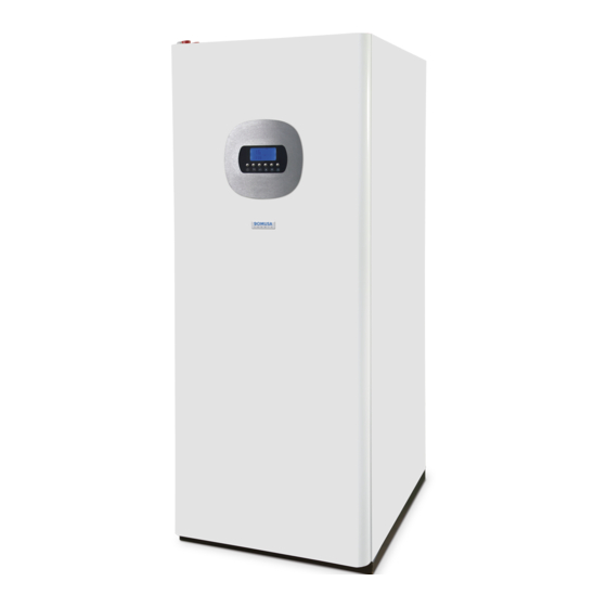
- Page 2 Thank you for choosing a DOMUSA TEKNIK heat pump accessory. You have chosen the FUSION model from the DOMUSA TEKNIK product line. This is an all-in-one hydraulic accumulation module, which in combination with a heat pump of the DUAL CLIMA line is able to provide the adequate level of comfort for your home, provided that the hydraulic installation is correctly performed.
-
Page 3: Table Of Contents
CONTENTS Page 1 SAFETY WARNINGS ..................................2 ................................2 SAGE AND INSTALLATION WARNINGS ....................................2 ERSONAL SAFETY WARNINGS 2 LIST OF COMPONENTS ................................3 3 INSTALLATION INSTRUCTIONS ..............................4 ......................................4 CCESSORIES UPPLIED .................................... -
Page 4: Safety Warnings
TEKNIK shall not be held liable for any damage that may occur due to failure to follow these instructions. The FUSION storage module can only be installed in combination with a heat pump from the DUAL CLIMA line from DOMUSA TEKNIK. The FUSION module, in combination with a DUAL CLIMA heat pump, is suitable for use in both heating and cooling installations, and can be combined with fan coils, underfloor heating/cooling and low-temperature radiators. -
Page 5: List Of Components
2 LIST OF COMPONENTS 1. DHW drain valve. 10. Connection strip. 2. Dielectric sleeve. 11. Heating backup heater E2 (Optional). 3. Filling disconnector. 12. DHW backup heater E1 (Optional). 4. DHW expansion vessel. 13. Installation backup pump C6 (Optional). 5. Control panel. 14. -
Page 6: Installation Instructions
FUSION HE 3 INSTALLATION INSTRUCTIONS The FUSION hydraulic module can only be installed in combination with a heat pump from the DUAL CLIMA line supplied by DOMUSA TEKNIK. Therefore, for their operation, these devices should be connected to each other, both hydraulically and electrically. In this section, the necessary operations for said connection are described in detail. -
Page 7: Assembly Of The Dhw Probe
“DHW TANK SENSOR”. For correct assembly, the probe must be guided to where the FUSION module has been placed and inserted into the bulb sheath provided for it in the same, following the steps indicated below: 1.- Remove the access cover to the tank, located on... -
Page 8: Assembly And Connection Of The Control Panel
The control panel is supplied inside the heat pump and must be mounted on the front of the FUSION hydraulic module. To do this, remove the front and access the electrical cabinet located at the back. For its correct assembly, please carefully follow the following steps: 1.- Loosen the wing nuts indicated in the figure. -
Page 9: Connecting The Dhw Diverter Valve (G1)
DUAL CLIMA heat pump to the inside of the FUSION module. The hydraulic module has a series of cable ducts in its roof, through one of which it will be possible to introduce the cable inside the equipment. -
Page 10: Filling The Installation
FUSION HE 3.6 Filling the installation The FUSION hydraulic module has a filling disconnector and a manometer, by means of which the water filling of the complete Heating/Cooling system can be carried out, including the external unit and the exchanger of the DHW cylinder. In turn, the hydraulic installation should incorporate the drain valves and hydraulic components necessary for its correct filling. -
Page 11: Optional Accessories
DUAL CLIMA heat pump components. To do this, an electrical hose (supplied in the DOMUSA TEKNIK heater kit) should be carried from the FUSION module to the heat pump, located on the outside. The hydraulic module has a series of cable ducts in its roof, through one of which it will be possible to remove the hose from inside the equipment. -
Page 12: Assembly And Connection Of A Backup Heater For Heating (E2)
DUAL CLIMA heat pump components. To do this, an electrical hose (supplied in the DOMUSA TEKNIK heater kit) should be carried from the FUSION module to the heat pump, located on the outside. The hydraulic module has a series of cable ducts in its roof, through one of which it will be possible to remove the hose from inside the equipment. -
Page 13: Assembly And Connection Of A Backup Pump (C6)
For installation, a spool is installed in the return pipe of the heating/cooling system inside the FUSION module for assembly of the optional pump offered by DOMUSA TEKNIK. To do this, first cut the insulating shell that covers the spool, disassemble it and seal the pump in place: 1.- Cut the insulating shell covering the spool and remove it, as... -
Page 14: Heating Expansion Vessel
Heating/Cooling system, the FUSION hydraulic module allows the installation of an 8-litre expansion vessel kit (optionally supplied) inside it. For its correct assembly inside the FUSION module, once it is ensured that the heating/cooling system is empty, please carefully follow the steps indicated in the following figures: 1.- Cut the insulation to access the plug of the expansion... -
Page 15: Recycling And Disposal
6 RECYCLING AND DISPOSAL Uninstallation This product should be uninstalled by authorised personnel for the handling of fluorinated gases. The heat pump contains R410A refrigerant. Any leakage of refrigerant into the atmosphere should be avoided. Recycling For recycling or disposal, the heat pump must be taken to a waste collection point. Contact qualified personnel for the handling of fluorinated gases. -
Page 16: Electrical Diagram
FUSION HE 7 ELECTRICAL DIAGRAM V3V: 3-way reversing valve. R: Relay. G1C/L: Heat Pump DHW signal (NC). G1O/S: Heat Pump Heating signal (NO). G1N/N: Heat Pump common signal (Neutral). -
Page 17: Diagrams And Measurements
8 DIAGRAMS AND MEASUREMENTS Front view Top view FUSION HE 150 FUSION HE 200 FUSION HE 300 (mm) (mm) (mm) Total height 1560 1965 1995 Rack height 1475 1880 1910 Bottom IC: Heating/Cooling Flow, Ø22 (fitting 1” M). RC: Heating/Cooling Return, Ø22 (fitting 1” M). -
Page 18: Spare Parts List
FUSION HE 9 SPARE PARTS LIST Jackets... - Page 19 ZINC-PLATED SHEET METAL ROUND-HEADED SCREW PHILLIP WITH 6 CTOR000073 RIBBED WASHER 3.9x9.5 7 SELEDCL001 ELECTRICAL SHEET FUSION 8 SEXT000447 RIGHT SIDE JACKET FUSION HE 150 SEXT000455 RIGHT SIDE JACKET FUSION HE 200 SEXT000462 RIGHT SIDE JACKET FUSION HE 300 9 SEXT000449...
- Page 20 FUSION HE Main board N. Code Name 1 SCON002098 BOARD SUB-UNIT 2 SOPE000084 PAINTED EVOLUTION RC PUSH-BUTTON 3 SCHA012936 ELECTRICAL BOX ZINC-PLATED HEX-NUT WITH WASHER DIN-6923 4 CTOR000089 5 SCHA013293 SUPPORT COVER 6 CTOR000306 ZINC-PLATED WING NUT M4...
- Page 21 SAIS000281 PIPE INSULATION SHELL 19x22 SAIS000287 PIPE INSULATION SHELL 9x12 SCON002011 VALVE AND DRUM COVER FUSION SAIS000283 PIPE INSULATION SHELL 19x22 FUSION HE 150 SAIS000285 PIPE INSULATION SHELL 9x22 SAIS000297 PIPE INSULATION SHELL 19x22 FUSION HE 200 SAIS000280 PIPE INSULATION SHELL 19x22 FUSION HE 150...
- Page 22 FUSION HE Pipe fittings FUSION HE 150/200...
- Page 23 Name N. Code Name 1 SCON002016 SUB-UNIT 32 SCON002104 TEMPERATURE SENSOR POCKET FUSION HE 150 2 CFOV000162 BELPA GASKET CSA-50 30x20x3 (1") SCON002105 TEMPERATURE SENSOR POCKET FUSION HE 200 3 SCOB012917 BOILER RETURN FUSION HE 150 33 SCON001191 ELIPTIC CAP SCOB012922 BOILER RETURN FUSION HE 200 34 CFOL000054 BRASS FEMALE CAP 1/2"...
- Page 24 FUSION HE Pipe fittings FUSION HE 300 57 55 55 56...
- Page 25 HEAD M5x10 8 CVAL000068 3-WAY DIVERTER VALVE 1" 50 SCOB012984 DRAINAGE 9 CTOR000103 ZINC-PLATED FLAT WASHER DIN-125A M8 51 SCHA013572 DRAINAGE SUPPORT FUSION HE 300 ELBOW WITH BRASS-NUT MALE THREAD 1"- 52 CVAL000034 DRAINAGE TAP WITH CHAIN M 1/2" 10 CFOL000126 LOOSENUT 1"...
- Page 26 FUSION HE Sub-units SCON002012 SCON002013 / SCON002036 SCON002016 N. Code Name 1 CFOL000009 BRASS NIPPLE 1/2"x3/4" 2 CFOL000006 BRASS NIPPLE 3/4" 3 CFOL000050 BRASS 3-WAY ELBOW 3/4" 4 CFOL000014 BRASS HEXAGONAL BUSH 1/2"x3/4" 5 CFOL000003 BRASS LOOSE NUT 25x1" 6 CFOV000064 PTFE BOTTOM GASKET PL/317-P 7 CTOE000071 HEXAGONAL NIPPLE WITH FLANGE 1/2"...
- Page 27 N. Code Name 1 SCON002099 BOARD SUB-UNIT 2 CELC000144 WHITE PRESSURE GAUGE Ø40x1.5 M 3 CFER000062 CABLE GROMMET REF. 210 Ø22 4 CTOR000091 ZINC-PLATED SHEET METAL ROUND-HEADED SCREW PHILLIP DIN-7981 3.2x9.5 5 CELC000006 RELAY 6 CMAZ000145 ELECTRICAL HARNESS FUSION HE...
- Page 28 Apartado 95 Bº San Esteban s/n 20730 AZPEITIA 20737 RÉGIL (Gipuzkoa) Spain Spain Tel: +34 943 813 899 www.domusateknik.com *CDOC001915* DOMUSA TEKNIK reserves the right to make modifications of any kind to 27/11/20 CDOC001915 its product characteristics without prior notice.
Need help?
Do you have a question about the FUSION and is the answer not in the manual?
Questions and answers