
Subscribe to Our Youtube Channel
Related Manuals for Oriental motor SUPER VEXTA U1215GA

Summary of Contents for Oriental motor SUPER VEXTA U1215GA
- Page 1 (217) 352-9330 | Click HERE Find the Oriental Motor UI215GA at our website:...
- Page 2 VEXTA OPERATOR'S MANUAL MODEL U1215GA INTELLIGENT STEP MOTOR DRIVER MODEL DP-01 DATA PACK O R I E N T A L O L MOTOR A r v I c 3 s , T , R 9 , 1 , ® Manual Number M91UI215GA-3...
-
Page 3: Table Of Contents
Please read this manual carefully, and use this product according to these instructions. I f you have any further questions, please do not hesitate to call Oriental Motor for assistance. TABLE OF CONTENTS The UI215GA Intelligent Step Motor Driver... -
Page 4: The Ui215Ga Intelligent Step Motor Driver
THE UI215GA INTELLIGENT STEP MOTOR DRIVER SUPER VEXTA's Intelligent Step Motor Driver combines a high performance unipolar chopper step motor driver and microprocessor intelligence, and is designed to interface easily with Program- mable Controllers or other switch-output type controllers (relay contact or open-collector outputs, for example). -
Page 5: Step Motor-Based Motion Control System
STEP MOTOR-BASED MOTION CONTROL SYSTEM C OtOt‘;00f1f).11(N-g6,,, The basic components of an open loop step motor based set, and by using the built in microprocessor, cal- motion system are shown in figure 1. culates the step and direction signals (motion pro- file) to be sent to the driver. -
Page 6: Ui215Ga And Dp-01 Layout
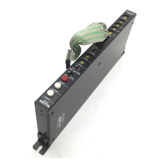
UI215GA & DP-01 LAYOUT Mode (Operating mode) Intelligent Driver Data Pack Index U1215GA DP-01 Return to Electrical Home Continuous Running/Home Hunting INTELLIGENT DRIVER 6 1 DATA PAC UI215GA DP-01 POWER • READY • Pulse (Number of steps) Number of steps in index move TIMING •... -
Page 7: Contents Included In This Package
CONTENTS INCLUDED IN THIS PACKAGE UI215GA Unit ACCESSORIES: External Controller 1 p c PCA-36FES Solder Type Connector (CN1) H o n d a Tsushin Kogyo Co., Ltd 4 1 0 1 1 1 1 1 1 1 0 0 1 N O M M I A External Controller 2 p c P C A - 3 6 L S M Connector Case Tsushin Kogyo Co., Ltd... -
Page 8: Motors That Can Be Used With The Ui215Ga
MOTORS THAT CAN BE USED WITH THE UI215GA The UI215GA intelligent step motor driver has a maximum current output of 1.25A/phase (2.5A total). Therefore, only the motors listed below are recommended for use with the UI215GA. These motors are recommended due to their winding characteristics. The use of any other motors with the UI215GA driver may damage the driver, the step motor or both. -
Page 9: Installation
INSTALLATION INSTALLING THE MOUNTING BRACKETS Use the metal brackets and screws provided to install the unit. The UI215GA can be mounted in either a Rear, Front, Side, Bottom or Top mounting configuration as show in the figures below. Front Side Rear Mounting Mounting... - Page 10 UI215GA CONNECTING TO THE MOTOR Yellow — Y E L L O W With no power connected to the driver, securely WHITE 2 Phase attach the colored motor lead wires to the corre- Step Motor BLACK sponding terminals on the UI215GA (See the with 6 lead wires drawings to the right for connecting either a 6 lead...
- Page 11 SWITCH SELECTABLE FEATURES SETTING T H E A.C.D. FUNCTION SWITCH: INTELLIGENT DRIVER UI215GA The A.C.D. function turns "ON" or "OFF" the POWER • ACD (AUTO CURRENT DOWN) automatic current cutback function that is built function override switch READY • into the Intelligent Driver unit. When the A.C.D. TIMING •...
- Page 12 OVERHEAT PROTECTION (AUTO- MATIC THERMAL-CUTOUT: AHO) When the temperature of the heat sink inside the driver reaches approximately 176°F (80°C), the INTELLIGENT DRIVER motor output current is automatically shut off, the U1215GA alarm indicator on the front panel lights up, and the POWER •...
-
Page 13: Setting The Run And Stop Current Levels
SETTING THE RUN AND STOP CURRENT LEVELS SETTING THE RUN CURRENT LEVEL Intelligent Driver U1215GA The UI215GA is shipped with the Run current po- POWER 0 tentiometer turned all the way down to its mini- READY 0 mum. The motor will not run properly in this con- Run Potentiometer for adjusting TIMING 0 dition. - Page 14 SETTING THE STOP CURRENT LEVEL Intelligent Driver U1215GA After setting the motor running current, turn POWER 0 the ACD function switch to the "ON" position READY 0 and set the motor stopped current value by Run Potentiometer for adjusting TIMING 0 the current value when the motor using the STOP potentiometer to approximately is running...
-
Page 15: Controlling The Ui215Ga Intelligent Driver
CONTROLLING THE UI215GA INTELLIGENT DRIVER The UI215GA can be controlled in three main configurations: 1) Completely controlled by an external controller (e.g. programmable controller), 2) Completely controlled by the DP-01 Data Pack or 3) Controlled in parallel by both the DP-01 Data Pack and an external controller. The figures below show the UI215GA Intelligent Driver being controlled in the various configurations. -
Page 16: External Control Of The Ui215Ga
EXTERNAL CONTROL OF THE UI215GA The UI215GA can be controlled by an external source such as a Programmable Controller, binary coded decimal (BCD) thumbwheel switches, other dry contact switches or open-collector transistor switches. All of the motion data; starting speed, running speed, acceleration/deceleration rate, direction, length of travel and the operating mode can be set by simply turning "ON"... -
Page 17: Description Of Signals
Description of Signals An input signal is considered to be "ON" when there is continuity to ground (Pin #31). An output signal is considered to be "ON" when it is LOW or CLOSED. Connector CN1 and CN2 Input/Output Signals Pin # Input/ Note Name of Signal... - Page 18 Table 1: Setting the Speed Range T a b l e 3: Setting the Acceleration/Deceleratior The Speed Range is designated to be "Low Speed" when ignal Rate Rate Speed Range the switch is in the "L" position and designated to be "High Low speed High speed Remark...
- Page 19 WIRING THE UI215GA TO A PROGRAMMABLE CONTROLLER Programmable Controller U1215GA 1 0 V D C Relay O R Transistor CN-1 2 . 2 k contact o u t p u t . . V . 1 ! I N D E X D A T A 1 BCD input lines for I N D E X D A T A 2 the l's digit...
- Page 20 SETTING THE MOTION DATA SELECTING THE OPERATING MODE The UI215GA can operate in four different modes: Index, Return to Electrical Home, Jog and Continuous Running/Mechanical Home Position Hunting modes. Connections for selecting the INDEX mode (mode 0) MODE 0 OR INDEX MODE "...
- Page 21 SELECTING THE OPERATING MODE (CONT.) Connections for selecting the JOG mode (mode 2) 3 1 1'0 Jog mode MODE 2 OR JOG MODE dope When the Jog Mode is selected (pin #24 "OFF" and Motor Motion 25 E D .1111111• 111111M•...
-
Page 22: Home Hunting With The Ui215Ga And A Plc1
HOME HUNTING WITH THE UI215GA AND A PLC The UI215GA Intelligent Driver can hunt for a mechanical home position limit switch with the help of a programmable controller (PLC). With the UI215GA in the Continuous Running Mode (mode 3), the CCW, S-STOP and RESET (used as the home position limit switch) lines can be used as control lines to a PLC to enable the UI215GA to hunt for a mechanical home position limit switch. -
Page 23: Improving The Accuracy Of The Home Position2
IMPROVING THE ACCURACY OF THE HOME POSITION 1) HOMELS "AND" TIMING The accuracy of your HOMELS can be improved if MOTOR MOTION you define the mechanical home position to be the logical "AND" of the HOMELS and the TIMING (Phase 0) output of the UI215GA driver. Since the step motor phase excitation sequence is repeated every four full steps (eight half steps), this signal will be output every 7.2°( 3.6°... -
Page 24: Selecting The Number Of Steps In An Index Move2
SETTING THE MOTION DATA (CONT.) Connections for selecting 6,798 SELECTING THE NUMBER OF STEPS 7.00 = steps in an index move IN AN INDEX MOVE 0 0 0 0 Setting the number of steps in an index move can be done by simply turning "ON"... -
Page 25: Selecting The Acceleration/Deceleration Rate2
Connections for the acce/decel functions SELECTING THE ACCELERATION/ DECELERATION RATE 0 0 0 0 There are 4 different accel/decel rates; Normal, Fast, 1 0 0 0 Slow and Constant (i.e. no acceleration) are available 0r. 0 0 in each speed range. To select an accel/decel rate, first 0 r 2 2 select a speed range (pin #17) and then select the 0 0 0 0... -
Page 26: S -Stop2
COMMAND FUNCTIONS (CONT.) S-STOP The S-STOP input line (pin "27) is used to slow down and then stop the motor depending on which operating Connection for the 0 0 0 0 mode (pins #24 and #25) the U1215GA is set to operate S-STOP function in. -
Page 27: Data Tables
CONTROL OF THE UI215GA WITH THE DP-01 DATA PACK The UI215GA can also be controlled by the DP-01 Data Pack alone to make a complete stand alone motion control system. All of the motion data; starting speed, running speed, acceleration/decelera- tion rate, direction, length of travel and the operating mode can be set by simply turning the dials or switches on the front panel of the DP-01 Data Pack. - Page 28 Table 1: Setting the Speed Range T a b l e 3: Setting the Acceleration/Deceleration The Speed Range is designated to be "Low Speed" Speed Range Rate when the switch is in the "L" position and desig- Low speed High speed Remark (m575000 pps) (ms/1000 pps)
-
Page 29: Data Pack Layout 2
DP-01 DATA PACK LAYOUT Mode (Operating mode) Data Pack Index DP-01 Return to Electrical Home Continuous Running/Home Hunting Pulse (Number of steps) Number of steps in index move 0 to 9,999 steps maximum Special cable/connector (Included with the DP-01) Range (Speed range) High/Low Speed Running speed... - Page 30 SETTING THE MOTION DATA SELECTING THE OPERATING MODE The UI215GA can operate in four different modes: Index, Return to Electrical Home, Jog and Continu- ous Running/Home Detection modes. MODE 0 OR INDEX MODE When the "START" button is depressed, the microproces- INDEX MODE INDEX MODE sor in the UI215GA reads all of data set on the DP-01 Data...
- Page 31 SELECTING THE NUMBER OF STEPS IN AN INDEX MOVE Setting the number of steps in an index move can be done by simply adjusting the four index dials on the front = 7,000 = 200 panel of the DP-01 Data Pack to the desired values. The number of steps in an index is expressed in 4 digits in decimal format and can be set for between 1-9,999 steps maximum.
- Page 32 COMMAND FUNCTIONS (CW/CCW, RESET, S-STOP, START AND SW CONTROL) C W / C C W The position of the CW/CCW switch determines the direction of rotation of the motor shaft as viewed from • 4 • • • . • • the mounting flange end of the motor.
-
Page 33: Precautions 3
PRECAUTIONS INSTALLATION OF THE DRIVER — Mounting tab Note: The driver uses natural convection for cooling. Be sure to provide sufficient air flow around the driver. 1) Install the driver on a highly heat-conductive base, such as metal, oriented vertically. 2) Keep the driver at least 1 inch away from any vertical obstructions, except for DP-01 which may be mounted flush against the driver. -
Page 34: Trouble Shooting The Ui215Ga
If your problem can not be solved with these sugggestions, please feel free to contact your local distributor, local Oriental Motor sales office or the Super Vexta Technical Support Group for further assistance. See page MOTOR DOES NOT MOVE I f the power light is "OFF▶▶... - Page 35 TROUBLE SHOOTING THE UI215GA (CONT.) See page MOTOR DOES NOT MAKE THE DESIRED MOVE I f the motor is not moving far enough ✓ I s connector CN1 miswired? page 21 ✓ I s connector CN2 not completely connected? page 24 ✓...
-
Page 36: Signal Timing Charts 3
SIGNAL TIMING CHARTS Timing for the Index Mode (Mode 0) move that is completed This chart represents the timing for a move with a preset length. Motion does not occur until the leading edge of a "START" signal is seen. 0.2ms or longer i b s START... - Page 37 Timing for the Return to Electrical Home Mode (Mode 1) This chart represents the timing for a move returning to the electrical home position (point where the internal counter = 0). Motion does not occur until the leading edge of a "START" signal is seen. 0.2ms or longer = 1 m s START...
- Page 38 Timing for the Continuous Running Mode (Mode 3) This chart represents the timing for a move that is continuously running (running until instructed to stop). Motion will not occur until the leading edge of a "START" signal is seen. If a "S-STOP" signal is input, the motor will decelerate to the base speed and continue running until a "RESET"...
-
Page 39: Speed Vs. Torque Characteristics 3
SPEED VS. TORQUE CHARACTERISTICS 1.8°/step type (200 steps/rev) P X 2 4 4 - O 2 B A P X 2 4 5 - 0 1 B A T 20 T 25 R 20 Q 15 — FULL S T E P —... - Page 40 0.9°/step type (400 steps/rev P X 2 4 5 M - 0 1 B A P X 2 4 4 M - 0 1 B A F U L L S T E P F U L L S T E P H A L F S T E P ----- H A L F S T E P To t a l C u r r e n t - 2 .
-
Page 41: Mechanical Dimensions 3
MECHANICAL DIMENSIONS UI215GA Unit = in(mm) Accessories (included) • Female Connector for CN1 • Mounting Bracket A PCA-36FES (Honda Tsushln Kogyo Co., Ltd.) .79(20)or less. Solder type 2 .14DIA.(03.5) _._.1.38(35) ___. Countersink .26DIA.(06.6) 2.49(63.2) - 4 4 - ( 2 ) .08 0 1 1 0 1 1 0 0 1 1 0 H F ..5 I „... - Page 42 2-phase Stepping Motors (Available separately) PX Type, Unit = inch(mm) Model L_.;1.65(. :42) PX244-02AA(BA) .39REF B - - - - - . . . 1 1.54 (39) 2.48 (63) I 2216°4 "7-.. (10REF) - A - - , . PX244M-01AA(BA u : - r <...
-
Page 43: Specifications 4
SPECIFICATIONS INTELLIGENT DRIVER UI215GA: Power Requirements: 115VAC ± 10%, <1.3 Amps 60 Hz Driver Type Unipolar Constant-Current Chopper (PWM) 1 Amp - 2.5 Amps total with two-phases "ON" Driver Output Power Driver Section 2-phases "ON" (Full Step) or Excitation Mode 1-2 phase "ON"... - Page 44 SPECIFICATIONS (CONT.) INTELLIGENT DRIVER UI215GA (CONT.): LED Indicators Power, Ready, Timing, Alarm Method of Cooling Convection Ambient Temperature 32° - 104°F (0° - 40°C) Range 1.8Ib (0.8kg) Weight Outer Dimensions 1.4"(W) x 9.5"(H) x 4"(D) [35mm(W) x240mm(H) x 100mm (D)] Sufficient to withstand 1 KVAC applied for 1 minute, between the input Dielectric Strength power terminal and the case .
- Page 45 EXPRESS OR IMPLIED, INCLUDING, WITHOUT LIMITATION, ANY IMPLIED WARRANTY OF MERCHANTABILITY OR FITNESS FOR A PARTICULAR PURPOSE. Oriental Motor reserves the right to make engineering refinements without notice. ORIENTAL MOTOR ORIENTAL MOTOR U.S.A. CORPORATION Chicago Office:...
Need help?
Do you have a question about the SUPER VEXTA U1215GA and is the answer not in the manual?
Questions and answers