
Summary of Contents for Graham Vari Speed S1000
- Page 1 (217) 352-9330 | Click HERE Find the Graham Transmissions 176B1111 at our website:...
- Page 2 Graham TRANSMISSIONS, Inc. Installation, Operation and Maintenance Manual Vari Speed S1000 Instruction Manual chnology Group - Quality Instrumentation ... Guaranteed | (888) 88-SOURCE | www.
- Page 3 chnology Group - Quality Instrumentation ... Guaranteed | (888) 88-SOURCE | www.
-
Page 4: Table Of Contents
TABLE OF CONTENTS Introduction Unit Features Operating Conditions Specifications Ratings Chart Dimensions Mounting & Installation Unit Functions Schematic Block Diagram Wiring Verification Test Component Location Set-Up Procedures Two-Speed Application Troubleshooting Guide Plug-On Terminal Option Available Options Warranty Details and specifications presented in this manual are subject to change without notice. -
Page 5: Introduction
INTRODUCTION The new Vari Speed S1000 is setting new standards in the field of inexpensive DC motor controllers. The smallest member of the Graham Transmissions, Inc. family includes features and performance only before thought possible in larger, more expensive units. By utilizing the latest in surface mount component technology and manufacturing processes, this controller is unsurpassed in performance and reliability. -
Page 6: Unit Features
UNIT FEATURES The following features are standard on all Vari Speed S1000 DC controls: • Surface mount technology - reduces size, improves performance and reliability. • Power supply uses control transformer and voltage regulators for optimum performance. • Full wave bridge rectifier with free-wheeling diode for optimum performance. -
Page 7: Operating Conditions
OPERATING CONDITIONS AC Line Voltage Variation Rated Voltage ( + / - 1 0 % ) AC Line Frequency 48 to 62 HZ Ambient Temperature 3 2° F to 131° F ( 0° C to 55° C) Elevation Up to 3000 Feet (1000 meters) without aerating NOTE: The Ambient Temperature specification is referring to the... -
Page 8: Specifications
CONTROL SPECIFICATIONS Service Factor 1 . 0 Form Factor 1 . 3 5 Duty Continuous Overload Capability 150% for 1 minute Speed Regulation 2% of Base Speed (for 95% Load Change) Speed Range 50:1 @ Full Torque Speed Potentiometer 5k ohm, 1W available accessory Process Signal Input 0-5VDC or O-10VDC (See Wiring and Warning on pg. - Page 9 chnology Group - Quality Instrumentation ... Guaranteed | (888) 88-SOURCE | www.
-
Page 10: Dimensions
DIMENSIONS chnology Group - Quality Instrumentation ... Guaranteed | (888) 88-SOURCE | www. - Page 11 Read all warnings and notes before proceeding to install or operate this control. The Vari Speed S1000 should be mounted in an enclosure appropriate for the application’s environment. Failure to do so could cause equipment malfunction or serious personal injury.
- Page 12 FOLLOW INSTRUCTION MANUAL, LOCAL, STATE, AND NATIONAL SAFETY CODES FOR PROPER INSTALLATION. ALWAYS DISCONNECT POWER TO THE CONTROL BEFORE MAKING ANY WIRING CHANGES, OR BEFORE INSPECTING EQUIPMENT. 2 . It is strongly recommended that the “L” bracket or heatsink of the unit is mounted to a grounded surface. 3 .
- Page 13 Motor overload protection must be provided by the equipment manufacturer or person installing controls per National Electrical Code. chnology Group - Quality Instrumentation ... Guaranteed | (888) 88-SOURCE | www.
-
Page 14: Unit Functions 1
UNIT FUNCTIONS RUN/STOP: A closed contact between the RUN and V+ will start the control as long as the INHIBIT is not activated. At the time of the START command, the unit will follow the adjustable ACCEL ramp to the Speed Input setting. - Page 15 *Verify that INHIBIT Is properly wired for application. See pages 14 & 15 for details. NOTES: 1. Factory set at 0 Vdc. 2 . Factory set for 90 Vdc for 120V controllers, 180 V dc for 240 V controllers. 3 . Factory set for 100% of controller rating. 4 .
- Page 16 chnology Group - Quality Instrumentation ... Guaranteed | (888) 88-SOURCE | www.
- Page 17 UNIT FUNCTIONS CONTINUED To program the S1000 for either a NO or NC type INHIBIT conditions, the unit’s logic should be set with Jumper J1. Jumper J1 is a 10K ohm; 1/4 watt resistor which is located between the inhibit and SP2 terminals on the S1000 circuit board. See Component Location page 21 for further information.
- Page 18 Jumper J1: IN Place* Jumper 1: Cut INH-Activated during OPEN INH-Activated during a CLOSED condition, must be CLOSED condition, must OPEN for for unit to RUN unit to RUN RUN-Close to RUN; Open to RUN-Close to RUN; Open to Stop STOP *Factor installed Note: In the CLOSED method, the RUN (green) LED will remain lit...
-
Page 19: Wiring 1
WIRING 1 . Refer to Ratings Chart (pg 8) for incoming line current and fuse rating. It is the responsibility of the user or person installing the controller to provide branch circuit protection according to NEC and local codes. On controllers using 120 VAC input, be sure the incoming hot lead is connected to L1 and common is connected to L2. -
Page 20: Verification Test 1
6 . WARNING: ALL TERMINALS OF THE UNIT ARE AT LINE POTENTIAL AND CAN BE EXTREMELY: HAZARDOUS. POWER MUST BE REMOVED FROM UNIT BEFORE ANY WIRES ARE CONNECTED. FAILURE TO COMPLY MAY RESULT IN PERSONAL INJURY, EQUIPMENT FAILURE, OR BOTH. 7 . - Page 21 2 . Set the Speed Pot to Minimum Speed (CCW), and place the external RUN/STOP switch in the STOP position 3 . Apply power to the control. Place the RUN/STOP switch in the RUN position. The RUN (green) LED should glow, but the motor should not turn.
-
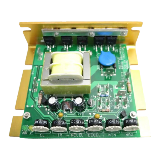
Page 22: Component Location 2
COMPONENT LOCATION chnology Group - Quality Instrumentation ... Guaranteed | (888) 88-SOURCE | www. -
Page 23: Set-Up Procedures 2
SET-UP PROCEDURES The Vari Speed S1000 has been set up at the factory to satisfy most application needs. You may, however, wish to tailor your control specifically to your application requirements. If so, follow these instructions for proper set-up. FACTORY SETTINGS... - Page 24 CURRENT (TORQUE) LIMIT ADJUST (CL) (Clockwise Increases Current) There are two methods for adjusting CL. METHOD 1: 1 . Start the machine and run at desired speed, then apply maximum load to the motor and turn CL trimpot fully clockwise. 2 .
- Page 25 IR COMPENSATION ADJUSTMENT (IR) (Clockwise Increases Compensation) This adjustment is provided to overcome the motor’s natural tendency to slow down with increasing load. If improved load/speed performance is required, this adjustment may be used. NOTE: In order to optimize performance with this adjustment, some means of determining motor shaft speed is required.
- Page 26 MINIMUM SPEED ADJUSTMENT (MIN) (Clockwise Increases Minimum Speed) 1 . Turn external Speed Pot fully counterclockwise (CCW). 2 . Turn MAX Speed Trimpot fully CCW. 3 . Produce a RUN command so that the RUN LED (green) is on and adjust the MIN SPEED trimpot until desired minimum speed is set.
- Page 27 ACCELERATION (ACCEL)/ DECELERATION (DECEL) ADJUSTMENTS Set these two trimpots for desired times. Both ACCEL and DECEL trim pots adjust from a linear .5 to 15 seconds. Acceleration rate may be extended with CL if reflected inertia is high. DECEL may be longer if reflected inertia is high.
-
Page 28: Two-Speed Application 2
TWO-SPEED APPLICATION By using single-pole, double throw (SPDT) relay or switch, preset two-speed operation is possible. 1 . Replace external speed pot with SPDT contacts as shown below. 2. With SPDT contacts closed between terminals SP2 and SP3, adjust the MIN SPEED trimpot to desired low speed. 3. -
Page 29: Troubleshooting Guide 2
TROUBLESHOOTING GUIDE MOTOR WILL NOT RUN: 1 . Make sure power is applied to unit. If not, make sure disconnect fuses or circuit breaker in line are okay. 2 . Make sure RUN switch is on (RUN (green) LED should be lit). 3 . - Page 30 NO SPEED CONTROL: 1 . Speed pot or wiring defective. 2 . Control not set up properly (See Set-Up Procedures, pg 22) 3 . Defective control. MOTOR WILL NOT RUN AT 1725 RPM: 1 . Improper setting MAX Speed trimpot (range trimpot with isolated units).
-
Page 31: Plug-On Terminal Option 3
PLUG-ON TERMINAL OPTION The Plug-On Terminal board provides for easy wiring for standard 14-20 AWG wire. 1 . Refer to drawing below for proper terminal wiring. NOTE: Wiring to Terminal Board before installation to Vari Speed S1000 may simplify procedure. 2 . - Page 32 AVAILABLE OPTIONS FOR VARI SPEED S1000 P l u g - o n T e r m i n a l B o a r d : 176B1113, 120 VAC or 176B1114, 240 VAC • Allows termination of stripped 14 to 20 AWG (lugless) wires.
-
Page 33: Warranty 3
WARRANTY Graham Transmissions, Inc. will make repairs to a product if the product meets the following warranty guidelines as determined by the date stamped on the product. • 12 months on DC Motors; a maximum of 12 months from the date of the invoice. - Page 34 Graham Transmissions, Inc. neither assumes nor authorizes any other person, firm or corporation to assume for it any other liability in connection with this sale. Graham Transmissions, Inc. shall not be held responsible for damage to person, or property, consequential loss, loss or profit, losses on...
- Page 35 chnology Group - Quality Instrumentation ... Guaranteed | (888) 88-SOURCE | www.
- Page 36 chnology Group - Quality Instrumentation ... Guaranteed | (888) 88-SOURCE | www.
- Page 37 N93 W14575 Whittaker Way Graham Menomonee Falls, WI 53051 TRANSMISSIONS, Inc. (888) 363-1313 01/00 Revision: A 176R0104 chnology Group - Quality Instrumentation ... Guaranteed | (888) 88-SOURCE | www.
Need help?
Do you have a question about the Vari Speed S1000 and is the answer not in the manual?
Questions and answers