Table of Contents
Advertisement
Quick Links
FCC Part 15
EMI TEST REPORT
E.U.T.
Model
FCC ID : 2AF4U022004001
APPLICANT
ADDRESS
ELECTRONICS TESTING CENTER, TAIWAN
NO. 34. LIN 5. DINGFU VIL., LINKOU DIST.,
NEW TAIPEI CITY, TAIWAN, 24442, R.O.C.
Tel : (02)26023052
http://www.etc.org.tw ; e-mail: emc@etc.org.tw
Report Number : 15-10-RBF-004-03
of
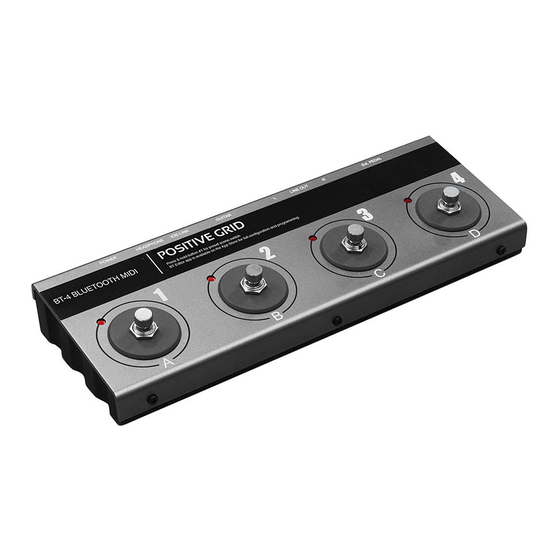
: BT-4 Pedal
: BT-4
for
: Positive Grid Digital Technology Co., Ltd.
: 10F., No.27-7, Yunong Rd., East Dist., Tainan
City 70164, Taiwan
Test Performed by
Fax : (02)26010910
Rev. No 2.0
Advertisement
Table of Contents

Subscribe to Our Youtube Channel
Summary of Contents for Positive Grid BT-4
- Page 1 : BT-4 Pedal E.U.T. : BT-4 Model FCC ID : 2AF4U022004001 APPLICANT : Positive Grid Digital Technology Co., Ltd. ADDRESS : 10F., No.27-7, Yunong Rd., East Dist., Tainan City 70164, Taiwan Test Performed by ELECTRONICS TESTING CENTER, TAIWAN NO. 34. LIN 5. DINGFU VIL., LINKOU DIST., NEW TAIPEI CITY, TAIWAN, 24442, R.O.C.
- Page 2 ETC Report No. : 15-10-RBF-004-03 FCC ID: 2AF4U022004001 TEST REPORT CERTIFICATION Applicant : Positive Grid Digital Technology Co., Ltd. 10F., No.27-7, Yunong Rd., East Dist., Tainan City 70164, Taiwan Manufacturer : Positive Grid Digital Technology Co., Ltd. 10F., No.27-7, Yunong Rd., East Dist., Tainan City 70164, Taiwan...
- Page 3 ETC Report No. : 15-10-RBF-004-03 FCC ID: 2AF4U022004001 Date Test Item Received : Oct. 05, 2015 Date Test Campaign Completed : Oct. 13, 2015 Date of Issue : Nov. 30, 2015 Test Engineer : Vincent Chang , Engineer Approve & Authorized Signer : Shang-Sheng Liou, Section Manager EMC Dept.
-
Page 4: Table Of Contents
ETC Report No. : 15-10-RBF-004-03 FCC ID: 2AF4U022004001 Table of Contents Page 1 GENERAL INFORMATION....................... 1 1.1 Product Description........................1 1.2 Characteristics of Device ......................1 1.3 Test Methodology ........................1 1.4 Test Facility..........................1 2 PROVISIONS APPLICABLE...................... 2 2.1 Definition ............................. 2 2.2 Requirement for Compliance ....................... - Page 5 ETC Report No. : 15-10-RBF-004-03 FCC ID: 2AF4U022004001 8.3 Measurement Equipment ......................27 8.4 Measurement Data ........................28 9 100 BANDWIDTH OF BAND EDGES MEASUREMENT..........29 9.1 Standard Applicable ........................29 9.2 Measurement Procedure......................29 9.3 Measurement Equipment ......................29 9.4 Measurement Data ........................
-
Page 6: General Information
Power Supply : Battery DC1.5V*2pcs 1.2 Characteristics of Device The product is a BT-4 Pedal. 1. Turn on the power of BT Pedal 2. Turn on Bluetooth on iOS device to connect with BT Pedal 3. Tap on the Message Name to configure, or select the quick presets from the header 1.3 Test Methodology... -
Page 7: Provisions Applicable
ETC Report No. : 15-10-RBF-004-03 FCC ID: 2AF4U022004001 Sheet 2 of 46 Sheets 2 PROVISIONS APPLICABLE 2.1 Definition Unintentional radiator: A device that intentionally generates and radio frequency energy for use within the device, or that sends radio frequency signals by conduction to associated equipment via connecting wiring, but which is not intended to emit RF energy by radiation or induction. -
Page 8: Requirement For Compliance
ETC Report No. : 15-10-RBF-004-03 FCC ID: 2AF4U022004001 Sheet 3 of 46 Sheets 2.2 Requirement for Compliance (1) Conducted Emission Requirement Except for Class A digital devices, for equpment that is designed to be connected to the public utility (AC) power line, the radio frequency voltage that is conducted back onto the AC power line on any frequency or frequencies within the band 150kHz to 30MHz shall not exceed the limits in the following table, as measured using a 50μH/50 ohms line impedance stabilization network (LISN). - Page 9 ETC Report No. : 15-10-RBF-004-03 FCC ID: 2AF4U022004001 Sheet 4 of 46 Sheets (3) Antenna Requirement For intentional device, according to § 15.203, an intentional radiator shall be designed to ensure that no antenna other than that furnished by the responsible party shall be used with the device.
-
Page 10: Restricted Bands Of Operation
ETC Report No. : 15-10-RBF-004-03 FCC ID: 2AF4U022004001 Sheet 5 of 46 Sheets 2.3 Restricted Bands of Operation Only spurious emissions are permitted in any of the frequency bands listed below : 0.090 - 0.110 16.42-16.423 399.9-410 4.5-5.15 0.495 - 0.505 ** 16.69475 - 16.69525 608-614 5.35-5.46... -
Page 11: User Information
ETC Report No. : 15-10-RBF-004-03 FCC ID: 2AF4U022004001 Sheet 6 of 46 Sheets 2.5 User Information The users manual or instruction manual for an intentional or unintentional radiator shall caution the user that changes or modifications not expressly approved by the party responsible for compliance could void the user's authority to operate the equipment. -
Page 12: System Test Configuration
1 by transmitting mode. 3.2 Devices for Tested System Device Manufacture Model / FCC ID Cable Description BT-4 Pedal * Positive Grid Digital BT-4/ 0.8m Unshielded Audio Cable Technology Co., Ltd. 2AF4U022004001 Remark “*” means equipment under test. -
Page 13: Radiated Emission Measurement
ETC Report No. : 15-10-RBF-004-03 FCC ID: 2AF4U022004001 Sheet 8 of 46 Sheets 4 RADIATED EMISSION MEASUREMENT 4.1 Applicable Standard For unintentional radiator, the radiated emission shall comply with § 15.109(a). For intentional radiators, according to § 15.247 (a), operation under this provision is limited to frequency hopping and direct sequence spread spectrum, and the out band emission shall be comply with §... - Page 14 ETC Report No. : 15-10-RBF-004-03 FCC ID: 2AF4U022004001 Sheet 9 of 46 Sheets 5. Repeat step 4 until all frequencies need to be measured were complete. 6. Repeat step 5 with search antenna in vertical polarized orientations. 7. Check the three frequencies of highest emission with varying the placement of cables (if any) associated with EUT to obtain the worse case and record the result.
-
Page 15: Measuring Instrument
ETC Report No. : 15-10-RBF-004-03 FCC ID: 2AF4U022004001 Sheet 10 of 46 Sheets 4.3 Measuring Instrument The following instrument are used for radiated emissions measurement: Equipment Manufacturer Model No. Calibration Date Next Cal. Date Spectrum Analyzer Rohde & Schwarz FSP40 2015/07/06 2016/07/05 EMI Test Receiver... -
Page 16: Radiated Emission Data
Sheet 11 of 46 Sheets 4.4 Radiated Emission Data 4.4.1 RF Portion Site :CHAMBER #2 Date :2015-10-09 Limit :1G TO 40G PEAK Ant. Pol. :HORIZONTAL :BT-4 Pedal Model :BT-4 Power Rating :DC 1.5V BATTERY * 2 Temp. :28°C Engineer Humi. :68 % Test Mode... - Page 17 FCC ID: 2AF4U022004001 Sheet 12 of 46 Sheets Site :CHAMBER #2 Date :2015-10-09 Limit :1G TO 40G PEAK Ant. Pol. :VERTICAL :BT-4 Pedal Model :BT-4 Power Rating :DC 1.5V BATTERY * 2 Temp. :28°C Engineer Humi. :68 % Test Mode...
- Page 18 Sheet 13 of 46 Sheets 4.4.2 Radiated Eimssion of Restricted bands Site :CHAMBER #2 Date :2015-10-09 Limit :1G TO 40G PEAK Ant. Pol. :HORIZONTAL :BT-4 Pedal Model :BT-4 Power Rating :DC 1.5V BATTERY * 2 Temp. :28°C Engineer Humi. :68 % Test Mode :CH LO &...
- Page 19 FCC ID: 2AF4U022004001 Sheet 14 of 46 Sheets Site :CHAMBER #2 Date :2015-10-09 Limit :1G TO 40G PEAK Ant. Pol. :VERTICAL :BT-4 Pedal Model :BT-4 Power Rating :DC 1.5V BATTERY * 2 Temp. :28°C Engineer Humi. :68 % Test Mode :CH LO &...
- Page 20 Sheet 15 of 46 Sheets 4.4.3 Other Emission a) Emission frequencies below 1 GHz Site :OPEN SITE Date :2015-10-09 Limit Ant. Pol. :HORIZONTAL :BT-4 Pedal Model :BT-4 Power Rating :DC 1.5V BATTERY * 2 Temp. :28°C Engineer Humi. :68 %...
- Page 21 ETC Report No. : 15-10-RBF-004-03 FCC ID: 2AF4U022004001 Sheet 16 of 46 Sheets Site :OPEN SITE Date :2015-10-09 Limit Ant. Pol. :VERTICAL :BT-4 Pedal Model :BT-4 Power Rating :DC 1.5V BATTERY * 2 Temp. :28°C Engineer Humi. :68 % Test Mode...
-
Page 22: Field Strength Calculation
ETC Report No. : 15-10-RBF-004-03 FCC ID: 2AF4U022004001 Sheet 17 of 46 Sheets b) Emission frequencies Above 1GHz Radiated emission frequencies above 1 GHz to 25 GHz were too low to be measured with a pre-amplifier of 35 dB. 4.5 Field Strength Calculation The field strength is calculated by adding the Antenna Factor, High Pass Filter Loss(if used) and Cable Loss, and subtracting the Amplifier Gain (if any) from the measured reading. -
Page 23: Photos Of Radiation Measuring Setup
ETC Report No. : 15-10-RBF-004-03 FCC ID: 2AF4U022004001 Sheet 18 of 46 Sheets 4.6 Photos of Radiation Measuring Setup Rev. No 2.0... - Page 24 ETC Report No. : 15-10-RBF-004-03 FCC ID: 2AF4U022004001 Sheet 19 of 46 Sheets Rev. No 2.0...
-
Page 25: Conducted Emission Measurement
ETC Report No. : 15-10-RBF-004-03 FCC ID: 2AF4U022004001 Sheet 20 of 46 Sheets 5 CONDUCTED EMISSION MEASUREMENT 5.1 Description This EUT is excused from investigation of conducted emission, for it is powered by DC battery only. According to § 15.207 (d), measurements to demonstrate compliance with the conducted limits are not required for devices which only employ battery power for operation and which do not operate from the AC power lines or contain provisions for operation while connected to the AC power lines. -
Page 26: Antenna Requirement
ETC Report No. : 15-10-RBF-004-03 FCC ID: 2AF4U022004001 Sheet 21 of 46 Sheets 6 ANTENNA REQUIREMENT 6.1 Standard Applicable For intentional device, according to § 15.203, an intentional radiator shall be designed to ensure that no antenna other than that furnished by the responsible party shall be used with the device. -
Page 27: Emission Bandwidth Measurement
ETC Report No. : 15-10-RBF-004-03 FCC ID: 2AF4U022004001 Sheet 22 of 46 Sheets 7 EMISSION BANDWIDTH MEASUREMENT 7.1 Standard Applicable According to 15.247(a)(2), for direct sequence system, the minimum 6dB bandwidth shall be at least 500 kHz. 7.2 Measurement Procedure 1. -
Page 28: Measurement Data
ETC Report No. : 15-10-RBF-004-03 FCC ID: 2AF4U022004001 Sheet 23 of 46 Sheets 7.4 Measurement Data Test Date : Oct. 13, 2015 Temperature : 22 °C Humidity : 55 % Mode: Bluetooth BLE a) Channel Low: 6 dB Emission Bandwidth is 0.676 MHz b) Channel Mid: 6 dB Emission Bandwidth is 0.676 MHz c) Channel High: 6 dB Emission Bandwidth is 0.672 MHz f ... - Page 29 ETC Report No. : 15-10-RBF-004-03 FCC ID: 2AF4U022004001 Sheet 24 of 46 Sheets Mode: Bluetooth BLE / Channel Low RBW 100 kHz Marker 1 [T1 ] VBW 300 kHz -2.25 dBm 10 dBm 40 dB SWT 2.5 ms 2.402220000 GHz ndB [T1] 6.00 dB BW 676.000000000 kHz...
- Page 30 ETC Report No. : 15-10-RBF-004-03 FCC ID: 2AF4U022004001 Sheet 25 of 46 Sheets Mode: Bluetooth BLE / Channel Mid RBW 100 kHz Marker 1 [T1 ] VBW 300 kHz -2.82 dBm 10 dBm 40 dB SWT 2.5 ms 2.440212000 GHz ndB [T1] 6.00 dB BW 676.000000000 kHz...
- Page 31 ETC Report No. : 15-10-RBF-004-03 FCC ID: 2AF4U022004001 Sheet 26 of 46 Sheets Mode: Bluetooth BLE / Channel High RBW 100 kHz Marker 1 [T1 ] VBW 300 kHz -3.58 dBm 10 dBm 40 dB SWT 2.5 ms 2.479724000 GHz ndB [T1] 6.00 dB BW 672.000000000 kHz...
-
Page 32: Output Power Measurement
ETC Report No. : 15-10-RBF-004-03 FCC ID: 2AF4U022004001 Sheet 27 of 46 Sheets 8 OUTPUT POWER MEASUREMENT 8.1 Standard Applicable For direct sequence system, according to 15.247(b), the maximum peak output power of the transmitter shall not exceed 1 Watt. If transmitting antennas of directional gain greater than 6 dBi are used, the power shall be reduced by the amount in dB that the directional gain of the antenna exceeds 6 dBi. -
Page 33: Measurement Data
ETC Report No. : 15-10-RBF-004-03 FCC ID: 2AF4U022004001 Sheet 28 of 46 Sheets 8.4 Measurement Data Test Date : Oct. 13, 2015 Temperature : 22 °C Humidity : 55 % Measurement Procedure: 9.1.2 PKPM1 Peak power meter method Output Peak Power Channel Low:2402MHz -1.89 0.647... -
Page 34: 100 Khz Bandwidth Of Band Edges Measurement
ETC Report No. : 15-10-RBF-004-03 FCC ID: 2AF4U022004001 Sheet 29 of 46 Sheets 9 100 kHz BANDWIDTH OF BAND EDGES MEASUREMENT 9.1 Standard Applicable According to 15.247(c), if any 100 kHz bandwidth outside these frequency bands, the radio frequency power that is produced by the modulation products of the spreading sequence, the information sequence and the carrier frequency shall be either at least 20 dB below that in any 100 kHz bandwidth within the band that contains the highest level of the desired power or shall not exceed the general levels specified in §... -
Page 35: Measurement Data
ETC Report No. : 15-10-RBF-004-03 FCC ID: 2AF4U022004001 Sheet 30 of 46 Sheets 9.4 Measurement Data Test Date : Oct. 13, 2015 Temperature : 22 °C Humidity : 55 % Mode: Bluetooth BLE Lower Band Edge : All emissions in this 100kHz bandwidth are attenuated more than 20dB from the carrier. - Page 36 ETC Report No. : 15-10-RBF-004-03 FCC ID: 2AF4U022004001 Sheet 31 of 46 Sheets Bluetooth BLE / Channel Low RBW 100 kHz Marker 1 [T1 ] VBW 300 kHz -60.61 dBm 0 dBm 20 dB SWT 10 ms 2.369800000 GHz 1 PK VIEW 01-B -100...
- Page 37 ETC Report No. : 15-10-RBF-004-03 FCC ID: 2AF4U022004001 Sheet 32 of 46 Sheets Bluetooth BLE / Channel High RBW 100 kHz Marker 1 [T1 ] VBW 300 kHz -65.60 dBm 0 dBm 20 dB SWT 10 ms 2.512200000 GHz 02-B 1 PK VIEW 01-B...
-
Page 38: Power Density Measurement
ETC Report No. : 15-10-RBF-004-03 FCC ID: 2AF4U022004001 Sheet 33 of 46 Sheets 10 POWER DENSITY MEASUREMENT 10.1 Standard Applicable According to 15.247(d), for direct sequence systems, the transmitted power density averaged over any 1 second interval shall not be greater than 8 dBm in any 3 kHz bandwidth within these bands. -
Page 39: Measurement Data
ETC Report No. : 15-10-RBF-004-03 FCC ID: 2AF4U022004001 Sheet 34 of 46 Sheets 10.4 Measurement Data Test Date : Oct. 13, 2015 Temperature : 22 °C Humidity : 55 % Mode: Bluetooth BLE a) Channel Low: Maximun PSD is -13.83 b) Channel Mid: Maximun PSD is -14.39... - Page 40 ETC Report No. : 15-10-RBF-004-03 FCC ID: 2AF4U022004001 Sheet 35 of 46 Sheets Bluetooth BLE / Channel Low RBW 3 kHz Marker 1 [T1 ] VBW 10 kHz -13.83 dBm 10 dBm 40 dB SWT 135 ms 2.402052800 GHz 1 PK VIEW Center 2.402 GHz 120 kHz/...
- Page 41 ETC Report No. : 15-10-RBF-004-03 FCC ID: 2AF4U022004001 Sheet 36 of 46 Sheets Bluetooth BLE / Channel Mid RBW 3 kHz Marker 1 [T1 ] VBW 10 kHz -14.39 dBm 10 dBm 40 dB SWT 135 ms 2.440088800 GHz 1 PK VIEW Center 2.44 GHz 120 kHz/...
- Page 42 ETC Report No. : 15-10-RBF-004-03 FCC ID: 2AF4U022004001 Sheet 37 of 46 Sheets Bluetooth BLE / Channel High RBW 3 kHz Marker 1 [T1 ] VBW 10 kHz -15.71 dBm 10 dBm 40 dB SWT 135 ms 2.479992800 GHz 1 PK VIEW Center 2.48 GHz 120 kHz/...
-
Page 43: Out-Of-Band Conducted Emission Measurement
ETC Report No. : 15-10-RBF-004-03 FCC ID: 2AF4U022004001 Sheet 38 of 46 Sheets 11. OUT-OF-BAND CONDUCTED EMISSION MEASUREMENT 11.1 Standard Applicable According to 15.247(c), in any 100 kHz bandwidth outside the frequency band in which the spread spectrum or digitally modulated intentional radiator is operating, the radio frequency power that is produced by the intentional radiator shall be at least 20 dB below that in the 100 kHz bandwidth within the band that contains the highest level of the desired power, based on either an RF conducted or a radiated measurement. -
Page 44: Measurement Data
ETC Report No. : 15-10-RBF-004-03 FCC ID: 2AF4U022004001 Sheet 39 of 46 Sheets 11.4 Measurement Data Test Date : Oct. 13, 2015 Temperature : 22 °C Humidity : 55 % A. Bluetooth BLE Mode: Channel Low, Mid, High (a) 30 MHz to 1 GHz frequency band: All emissions are attenuated more than 20dB from the carrier. - Page 45 ETC Report No. : 15-10-RBF-004-03 FCC ID: 2AF4U022004001 Sheet 40 of 46 Sheets Bluetooth BLE 30 MHz to 1 GHz/ Channel Low RBW 100 kHz Marker 1 [T1 ] VBW 300 kHz -60.35 dBm 0 dBm 10 dB SWT 100 ms 127.000000000 MHz 1 PK VIEW...
- Page 46 ETC Report No. : 15-10-RBF-004-03 FCC ID: 2AF4U022004001 Sheet 41 of 46 Sheets Bluetooth BLE 30 MHz to 1 GHz/ Channel Mid RBW 100 kHz Marker 1 [T1 ] VBW 300 kHz -61.03 dBm 0 dBm 10 dB SWT 100 ms 127.000000000 MHz 1 PK VIEW...
- Page 47 ETC Report No. : 15-10-RBF-004-03 FCC ID: 2AF4U022004001 Sheet 42 of 46 Sheets Bluetooth BLE 30 MHz to 1 GHz/ Channel High RBW 100 kHz Marker 1 [T1 ] VBW 300 kHz -60.81 dBm 0 dBm 10 dB SWT 100 ms 127.000000000 MHz 1 PK VIEW...
- Page 48 ETC Report No. : 15-10-RBF-004-03 FCC ID: 2AF4U022004001 Sheet 43 of 46 Sheets Bluetooth BLE Above 1 GHz / Channel Low RBW 100 kHz VBW 300 kHz 0 dBm 10 dB SWT 2.6 s 1 PK VIEW 03-B -100 Start 1 GHz 2.55 GHz/ Stop 26.5 GHz Rev.
- Page 49 ETC Report No. : 15-10-RBF-004-03 FCC ID: 2AF4U022004001 Sheet 44 of 46 Sheets Bluetooth BLE Above 1 GHz / Channel Mid RBW 100 kHz VBW 300 kHz 0 dBm 10 dB SWT 2.6 s 1 PK VIEW 03-B -100 Start 1 GHz 2.55 GHz/ Stop 26.5 GHz Rev.
- Page 50 ETC Report No. : 15-10-RBF-004-03 FCC ID: 2AF4U022004001 Sheet 45 of 46 Sheets Bluetooth BLE Above 1 GHz / Channel High RBW 100 kHz VBW 300 kHz 0 dBm 10 dB SWT 2.6 s 1 PK VIEW 03-B -100 Start 1 GHz 2.55 GHz/ Stop 26.5 GHz Rev.
-
Page 51: Dyty Cycle
ETC Report No. : 15-10-RBF-004-03 FCC ID: 2AF4U022004001 Sheet 46 of 46 Sheets 12. DYTY CYCLE 12.1 Standard Applicable None. Refereency only. 12.2 Measurement Equipment Equipment Manufacturer Model No. Calibration Date Next Cal. Date Spectrum Analyzer Rohde & Schwarz FSP40 2015/07/06 2016/07/05 12.3 Measurement Data...
Need help?
Do you have a question about the BT-4 and is the answer not in the manual?
Questions and answers