
Related Manuals for Wilo TR 212 Series


Summary of Contents for Wilo TR 212 Series
- Page 1 Pioneering for You Wilo-EMU TR/TRE 212 ... 326-3 en Installation and operating instructions · 6088786 • Ed.02/2021-05...
-
Page 3: Table Of Contents
Operation in an explosive atmosphere ................................ 28 Before switching on...................................... 29 Switch on and off...................................... 29 During operation ...................................... 29 8 Shut-down/dismantling................................. 30 Personnel qualifications.................................... 30 Operator responsibilities.................................... 30 Shut-down........................................ 30 Removal.......................................... 31 Installation and operating instructions Wilo-EMU TR/TRE 212 ... 326-3... - Page 4 12.1 Oils and lubricants...................................... 42 12.2 Protective clothing ...................................... 42 12.3 Information on the collection of used electrical and electronic products.................... 43 13 Appendix.................................... 43 13.1 Tightening torques ...................................... 43 13.2 Frequency converter operation .................................. 43 13.3 Ex rating ........................................... 44 WILO SE 2021-05...
-
Page 5: General Information
Distribute any content. ƒ Use any content for competition purposes without authorisation. Wilo shall reserve the right to change the listed data without notice and shall not be li- able for technical inaccuracies and/or omissions. Subject to change Wilo shall reserve the rights to make technical changes to the product and individual components. - Page 6 General warning symbol Warning of cutting injuries Warning of hot surfaces Warning of high pressure Warning of suspended loads Personal protective equipment: wear a safety helmet Personal protective equipment: wear foot protection Personal protective equipment: wear hand protection WILO SE 2021-05...
-
Page 7: Personnel Qualifications
In case of sensitive mains, make provision for the installation on- site of other protective equipment (e.g. overvoltage, undervoltage or phase failure re- lay, etc.). Installation and operating instructions Wilo-EMU TR/TRE 212 ... 326-3... -
Page 8: Use In Fluids Hazardous To Health
If there is a risk of explosion, do not carry out welding work or work with electrical devices. ƒ Disconnect device from the mains and secure it against being switched on again without authorisation. ƒ All rotating parts must stop. WILO SE 2021-05... -
Page 9: During Operation
Train the personnel on how the system operates. ƒ Eliminate any risk from electrical current. ƒ Fit dangerous components within the system with an on-site guard. ƒ Demarcate and cordon off the working area. Installation and operating instructions Wilo-EMU TR/TRE 212 ... 326-3... -
Page 10: Application/Use
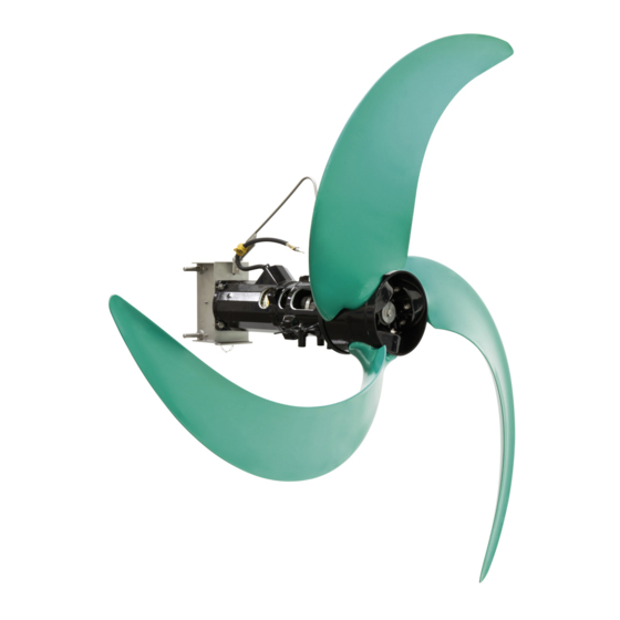
Fig. 1: Overview of the submersible mixer 4.1.1 Propeller Propeller made of solid or composite material, clogging-free thanks to backward- curved incoming flow edge. NOTICE! The propeller must not emerge during opera- tion. Observe the specified minimum water immersion according to the configura- tion! WILO SE 2021-05... - Page 11 * = motors in efficiency class IE4 have been specified as “E4” in the motor designation. ** = depending on the motor type and motor capacity fluid temperatures up to 60 °C (140 °F) are possible. 4.1.4 Seal The system is sealed by a 3-chamber system: ƒ Pre-chamber Installation and operating instructions Wilo-EMU TR/TRE 212 ... 326-3...
-
Page 12: Monitoring Devices
Once the low activation temperature has been reached, an automatic reactivation can be initiated after the motor has cooled down. The unit is forced to de- activate with reactivation lock once the high activation temperature has been reached. WILO SE 2021-05... -
Page 13: Operating Modes
Protection class: Explosion-proof ƒ Category: Class 1Division 1 Rating plate The following is an overview of the abbreviations and associated data on the rating plate: Rating plate Value designation P-Typ Mixer type Installation and operating instructions Wilo-EMU TR/TRE 212 ... 326-3... -
Page 14: Type Key
ƒ W = abbreviation for week ƒ ww = calendar week Type key Example: Wilo-EMU TRE 326-3.24-6/16R Ex X Submersible mixer, horizontal: ƒ TR = mixer with standard asynchronous motor ƒ TRE = mixer with asynchronous motors of motor efficiency class IE3/... -
Page 15: Transportation And Storage
The stability of the lifting equipment must be ensured during operation. ƒ When using lifting equipment, a second person must be present to coordinate the procedure if required (e.g. if the operator’s field of vision is blocked). Fig. 2: Attachment point Installation and operating instructions Wilo-EMU TR/TRE 212 ... 326-3... -
Page 16: Storage
Lifting work: trained specialist for the operation of lifting devices Lifting equipment, lifting gear, attachment points ƒ Operator responsibilities Observe locally applicable accident prevention and safety regulations. ƒ Observe all regulations for working with heavy loads and under suspended loads. WILO SE 2021-05... -
Page 17: Installation Types
Danger of (serious) injuries during work. Wear the following protective equipment: • Safety gloves for protection against cuts • Safety shoes • Safety harness • Safety helmet must be worn if lifting equipment is used! Installation and operating instructions Wilo-EMU TR/TRE 212 ... 326-3... - Page 18 ‡ The mixer is not connected to the mains! ‡ Protective equipment must be put on! 1. Place the mixer horizontally on a firm surface. WARNING! Risk of hands being crushed. Ensure that the mixer cannot fall over WILO SE 2021-05...
- Page 19 7. Clean the drain hole screw plug, replace the seal ring and screw it back in. Max. tightening torque: 8 Nm (5.9 ft·lb)! 8. Pour the operating fluid through the filler hole. ⇒ Comply with the specifications for the operating fluid type and quantity! Installation and operating instructions Wilo-EMU TR/TRE 212 ... 326-3...
- Page 20 4. Lay all connection cables. 5. Mount the cable bracket for the cable anchoring on the edge of the basin. CAUTION! In case of powerful flows in the basin, install the “additional rope an- choring”! Fig. 4: Prepare the mixer WILO SE 2021-05...
- Page 21 3. Version with quick-release axles: Lower mixer until the frame is below the upper holder. Install the quick-release axles and plastic rollers and secure them with linchpins! Fig. 6: Mixer on the lowering device Installation and operating instructions Wilo-EMU TR/TRE 212 ... 326-3...
- Page 22 5. Use the additional cable brackets to attach the connection cables to the nylon rope. Max. distance between the cable brackets: 1 m. CAUTION! The nylon rope may stretch in the water. When the nylon rope is taut, the connection cables must sag approximately 10 cm! WILO SE 2021-05...
-
Page 23: Electrical Connection
In case of sensitive mains, make provision for the installation on- site of other protective equipment (e.g. overvoltage, undervoltage or phase failure re- lay, etc.). Installation and operating instructions Wilo-EMU TR/TRE 212 ... 326-3... - Page 24 Electrical connection must always be carried out by a qualified electrician! NOTICE! The individual wires are designated according to the connection diagram. Do not cut the wires! There is no additional assignment between the wiring diagram and connection diagram. WILO SE 2021-05...
- Page 25 With PTC sensor Connect the PTC sensor via an evaluation relay. "CM-MSS" relay is recommended for this purpose. PTC sensor wiring diagram Temperature limiter 10, 11 PTC sensor connection Temperature controller and limiter Installation and operating instructions Wilo-EMU TR/TRE 212 ... 326-3...
- Page 26 Adjust the operating parameters of the frequency converter to the system paramet- ers. ƒ Observe the treatment process. Silting or deposits may occur. ƒ Increased thrust can lead to higher loads on the attachment parts. NOTICE! The operator is responsible for compliance with the treatment process! WILO SE 2021-05...
-
Page 27: Commissioning
View from front: The propeller rotates anti-clockwise (to the left). View from rear: The propeller rotates clockwise (to the right). ▶ Direction of rotation correct. Fig. 10: Correct direction of rotation TR/E 216 to 326-3 Installation and operating instructions Wilo-EMU TR/TRE 212 ... 326-3... -
Page 28: Operation In An Explosive Atmosphere
The mixers are suitable for operation in potentially explosive atmospheres: ƒ Protection class: Explosionproof ƒ Category: Class I, Division 1 Notice: If the cabling is carried out according to Division 1, installation in Class I, Di- vision 2 is also permitted. WILO SE 2021-05... -
Page 29: Before Switching On
Depending on the fluid and the flow, the current consumption may vary slightly. If cur- rent consumption is elevated for a longer period, this indicates a change in configura- tion. The cause for a change in conditions could be: Installation and operating instructions Wilo-EMU TR/TRE 212 ... 326-3... -
Page 30: Shut-Down/Dismantling
For an extended period of shutdown, carry out a function test at regular intervals: – Period: monthly to quarterly – Running time: 5 minutes – Only run a function test in valid operating conditions! CAUTION! Do not run when dry! Non-compliance can result in irreparable damage! WILO SE 2021-05... -
Page 31: Removal
Risk of burns from hot surfaces! Motor housing can become hot during operation. It may cause burns. Allow the mo- tor to cool down at ambient temperature after switching it off! Installation and operating instructions Wilo-EMU TR/TRE 212 ... 326-3... - Page 32 4. Spray the mixer with clear water from top to bottom. NOTICE! Use an appropriate disinfectant for contaminated mixers! Follow the specifications of work regula- tions! 5. Spray the propeller from all sides. 6. Flush dirt residues from the floor into the drain. 7. Allow the mixer to dry. WILO SE 2021-05...
-
Page 33: Maintenance And Repair
Shell: Omala S2 GX 220 ƒ Tripol: FoodProof 1810/220 (USDA-H1 approved) ƒ 9.3.2 Grease Esso: Unirex N3 ƒ Tripol: Molub-Alloy-Food Proof 823 FM (USDA-H1 approved) ƒ 9.3.3 Filling quantities Pre-chamber: 1.00 l (34 US.fl.oz.) Installation and operating instructions Wilo-EMU TR/TRE 212 ... 326-3... -
Page 34: Maintenance Intervals
Larger voltage fluctuations strain the motor winding and can cause breakdown. Regular inspections can therefore largely prevent major secondary damage and reduce the risk of total breakdown. In this regard, it is re- commended to use remote monitoring for regular inspections. WILO SE 2021-05... - Page 35 Changes caused by chemical corrosion If damage to the connection cable is identified, decommission the mixer immediately! Have the connection cable replaced by Wilo customer service. Only start the mixer up again once the damage has been properly remedied! CAUTION! Water can enter into the mixer if the connection cable is damaged! Water ingress leads to the mixer being written off.
- Page 36 NOTICE! Vacuum the oil or rinse the sealing chamber to fully drain the system. 5. Check the operating fluid: Notify customer service if the operating fluid contains metal swarf! 6. Dispose of operating fluid in accordance with local regulations! WILO SE 2021-05...
-
Page 37: Repairs
This threadlocker can be loosened with increased force. If the thread-locking fluid cannot be loosened, then the compound must be heated to ap- prox. 300 °C (572 °F). Clean the components thoroughly after dismantling. Installation and operating instructions Wilo-EMU TR/TRE 212 ... 326-3... - Page 38 262 or 2701. Press on the packing sleeve in position using a rubber mallet. 8. Install a new mechanical seal spring on the shaft. 9. Mount the propeller. ▶ Mechanical seal is replaced. Top up oil in the pre-chamber. WILO SE 2021-05...
- Page 39 - Screw on and fully tighten the hexagon nut. Max. tightening torque: see ap- pendix. 10.Check the shackle position! Attach the lifting equipment to shackles. The mixer must remain horizontal during lifting. Move shackles if the mixer tilts. ▶ Handle grip changed. Installation and operating instructions Wilo-EMU TR/TRE 212 ... 326-3...
-
Page 40: Faults, Causes And Remedies
Risk of death due to electrocution! Improper conduct when carrying out electrical work can lead to death due to electric shock! Electrical work must be carried out by a qualified electrician in accordance with the locally applicable regulations. WILO SE 2021-05... - Page 41 5. Incorrect direction of rotation. ⇒ Have the connection corrected by a qualified electrician. 6. Increased current consumption due to clogging. ⇒ Clean propeller and mechanical seal. ⇒ Check the pre-treatment. Installation and operating instructions Wilo-EMU TR/TRE 212 ... 326-3...
-
Page 42: Spare Parts
Operating fluid must be collected in suitable tanks and disposed of in accordance with the locally applicable guidelines. Wipe up drips immediately! 12.2 Protective clothing Used protective clothing must be disposed off in accordance with the locally applicable guidelines. WILO SE 2021-05... -
Page 43: Information On The Collection Of Used Electrical And Electronic Products
(50 Hz or 60 Hz) is adjusted to the power requirement of the mixer. More re- cent frequency converters feature an automatic power optimisation function - this Installation and operating instructions Wilo-EMU TR/TRE 212 ... 326-3... -
Page 44: Ex Rating
The mixers are suitable for operation in potentially explosive atmospheres: ƒ Protection class: Explosionproof ƒ Category: Class I, Division 1 Notice: If the cabling is carried out according to Division 1, installation in Class I, Di- vision 2 is also permitted. WILO SE 2021-05... - Page 45 ƒ Temperature limiter (1 temperature circuit): The unit must be deactivated with anti-reactivation lock once the trigger temper- ature has been reached! ƒ Temperature controller and limiter (2 temperature circuits): Installation and operating instructions Wilo-EMU TR/TRE 212 ... 326-3...
- Page 46 Carrying out repairs according to the values in tables 1 and 2 of DIN EN 60079-1 is not permitted. ƒ Only use screws as stipulated by the manufacturer, which at a minimum correspond to a strength class of 600 N/mm² (38.85 long tons-force/inch²). WILO SE 2021-05...
- Page 47 If the housing coating has to be repaired, the maximum coat thickness is 2 mm (0.08 in)! 13.3.6.2 Replacing the connection cable Changing the connection cable is strictly prohibited! 13.3.6.3 Changing the mechanical seal Changing the seal on the motor side is strictly prohibited! Installation and operating instructions Wilo-EMU TR/TRE 212 ... 326-3...
- Page 52 Local contact at www.wilo.com/contact WILO SE Wilopark 1 44263 Dortmund Germany T +49 (0)231 4102-0 T +49 (0)231 4102-7363 wilo@wilo.com Pioneering for You www.wilo.com...
Need help?
Do you have a question about the TR 212 Series and is the answer not in the manual?
Questions and answers