Table of Contents
Advertisement
Quick Links
Instruction Manual AVTM6514J
Catalog Nos. 651403 and 651404
Read the entire manual before operating.
Antes de operar este producto lea este manual enteramente.
for
Impulse Generator
High-Voltage Equipment
Aparato de Alto Voltaje
PO Box 9007
Valley Forge, PA 19485-1007 U.S.A.
610-676-8500
Shipping Address:
Valley Forge Corporate Center
2621 Van Buren Avenue
Norristown, PA 19403 U.S.A.
www.megger.com
AVTM6514J
Rev. A
March 2003
Advertisement
Table of Contents

Subscribe to Our Youtube Channel
Summary of Contents for Megger AVTM6514J
- Page 1 AVTM6514J Rev. A March 2003 Instruction Manual AVTM6514J Impulse Generator Catalog Nos. 651403 and 651404 High-Voltage Equipment Read the entire manual before operating. Aparato de Alto Voltaje Antes de operar este producto lea este manual enteramente. PO Box 9007 Valley Forge, PA 19485-1007 U.S.A.
- Page 2 If the product or its individual instruments are used for purposes other than those specified herein, confirmation of their validity and suitability must be obtained from Megger. Specifications are subject to change without notice. AVTM6514J Rev. A (03/2003)
-
Page 3: Table Of Contents
Operation With An Electromagnetic Impulse Detector ............... 22 Proof Testing Cable ............................ 22 SECTION 8 ................................23 Service................................23 Maintenance ..............................23 Performance Check............................. 24 Troubleshooting And Repair ........................25 SECTION 9 ................................29 Replaceable Parts List............................29 GLOSSARY ................................31 AVTM6514J Rev. A (03/2003) - Page 4 WARRANTY................................ 33 APPENDIX ................................35 Brief Operating Instructions........................35 FIGURE LIST Figure 1: Impulse Generator..........................2 Figure 2: Schematic Diagram..........................12 Figure 3: Typical Fault Diagram........................21 AVTM6514J Rev. A (03/2003)
-
Page 5: Section 1
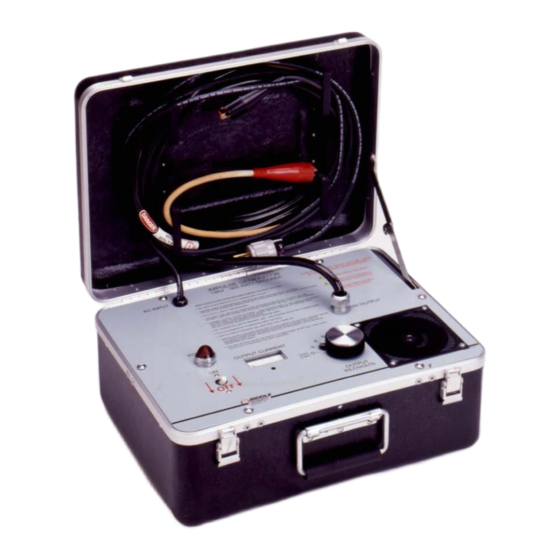
Notify Megger of any shortage. Telephone (610) 676-8500. Examine the instrument for possible damage received in transit. If any damage is discovered, file a claim with the carrier at once and notify Megger or its nearest authorized sales representative, giving a detailed description of the damage. - Page 6 Figure 1: Impulse Generator AVTM6514J Rev. A (03/2003)
- Page 7 ZERO START position which discharges the capacitors and provides a zero-voltage start-up for safety. Input and output cables are permanently attached; storage for cables is provided in the lid of the carrying case. An integral fan provides cooling. AVTM6514J Rev. A (03/2003)
- Page 8 AVTM6514J Rev. A (03/2003)
-
Page 9: Section 2
A safety ground jumper must then be installed between the high-voltage conductor and ground of the cable under test. The ground connection must be the first made and the last removed. AVTM6514J Rev. A (03/2003) - Page 10 As a routine safety procedure, however, some users require that rubber gloves be worn, not only when making connections to the high-voltage terminals, but also when manipulating controls. Megger recommends this excellent safety practice. AVTM6514J Rev. A (03/2003)
- Page 11 Megger has made formal safety reviews of the initial design and any subsequent changes. This procedure is followed for all new Megger products and covers areas in addition to those included in applicable ANSI standards. Regardless of these efforts, it is not possible to eliminate all hazards from electrical test equipment or to foresee every possible hazard that may occur.
- Page 12 AVTM6514J Rev. A (03/2003)
-
Page 13: Section 3
-22 to 131°F (-30 to 55°C) (storage) Altitude: 7500 ft (2286 m) maximum Voltage derates at higher altitudes Humidity: Operation and storage limits 5 to 95% rh noncondensing conditions Climate: Operation prohibited in rain or snow AVTM6514J Rev. A (03/2003) - Page 14 AVTM6514J Rev. A (03/2003)
-
Page 15: Section 4
Every six seconds a voltage pulse is discharged through transformer T2, gating pilot SCR Q6. In turn, Q6 switches the gating voltage to the main SCR Q7, thus completing the firing sequence for the high- voltage output pulses. AVTM6514J Rev. A (03/2003) - Page 16 Figure 2: Schematic Diagram...
-
Page 17: Controls And Connectors
0 to 15 kV in steps of 3 kV and also provides the ZERO START feature. OUTPUT CURRENT meter: indicates percentage of the maximum peak output current: 600 A at 15 kV into a short circuit AVTM6514J Rev. A (03/2003) - Page 18 AVTM6514J Rev. A (03/2003)
-
Page 19: Section 5
Do not extend the surge ground. Be sure that this connection is made to a secure low-resistance ground (less than 5O), usually the driven ground of the power system located in the vicinity of and connected to the specimen ground. AVTM6514J Rev. A (03/2003) - Page 20 Start the engine-generator and allow it to warm up sufficiently to ensure normal stable operation. e. Check the engine-generator voltage to ensure proper input voltage for the system. f. Connect the test system to the motor-generator using the input cord. AVTM6514J Rev. A (03/2003)
- Page 21 WARNING Do not refuel the engine-generator while it is running. When these setup procedures have been completed, the test may be conducted in accordance with the procedures given in Section 6. AVTM6514J Rev. A (03/2003)
- Page 22 AVTM6514J Rev. A (03/2003)
-
Page 23: Section 6
The meter is calibrated to produce full scale (approximately 100 percent) deflection with a 15 kV impulse into a short circuit. The reading is lower than AVTM6514J Rev. A (03/2003) -
Page 24: Shutdown Procedure
3. Remove the test clips from the conductor and the shield. WARNING Leave the safety ground jumpers in place to drain any relaxation charge for a period of at least four times as long as the test voltage had been applied. AVTM6514J Rev. A (03/2003) -
Page 25: Section 7
Basically, sparkover is determined by three factors: the nature of the fault, the capacitance of cable, and the capacitance of the Impulse Generator. If the capacitance of the Impulse Generator is equal to or smaller than that of the cable to which the AVTM6514J Rev. A (03/2003) -
Page 26: Impulse Testing
Advance the OUTPUT KILOVOLTS switch one step at a time until the cable withstands several 15 kV impulses. The fault may then be considered repaired and proof tested. AVTM6514J Rev. A (03/2003) -
Page 27: Section 8
2. Inspect and clean the outer jacket of the HV OUTPUT cable; check for breaks in this jacket. As a temporary repair, and only if the shield is intact, apply at least four layers of vinyl tape over any such damage. Replace the damaged output cable as soon as practical. AVTM6514J Rev. A (03/2003) -
Page 28: Performance Check
Fault characteristics can vary widely and in some cases can even temporarily clear themselves. The performance check can verify the proper performance of the Impulse Generator so AVTM6514J Rev. A (03/2003) -
Page 29: Troubleshooting And Repair
However, the problem can often be located with a few simple checks made by a technician using only a VOM multimeter. Repairs may be made in the field using components available from Megger. Refer to Section 9, Replaceable Parts List. - Page 30 Fan and POWER lamp come on, but no Fault meter, or malfunction in charging, meter indication. firing, or output circuits. Check test points on next page. AVTM6514J Rev. A (03/2003)
- Page 31 200 V dc at every step, up to approximately 900 V dc at 15 kV. Return the OUTPUT KILOVOLTS switch to ZERO START. This checks the dc supply to the high-voltage section. AVTM6514J Rev. A (03/2003)
- Page 32 The problem might also be in the capacitor bank C7; check for damaged components and replace as necessary. 7. Check the secondary of pulse transformer T3 for an open circuit or a short. Check current transformer T4, and check the circuitry feeding the meter. AVTM6514J Rev. A (03/2003)
-
Page 33: Section 9
Section 9 Replaceable Parts List The following lists all the parts that may need replacement during the life of the Impulse Generator. They are normally available from Megger. The Schematic Designation column refers to Figure 2. Megger SCHEMATIC DESCRIPTION DESIGNATION PART NO. - Page 34 AVTM6514J Rev. A (03/2003)
-
Page 35: Glossary
A disruptive discharge in the form of an arc or spark between two electrical conductors or between a conductor and earth (also called arc-over or flashover). AVTM6514J Rev. A (03/2003) - Page 36 AVTM6514J Rev. A (03/2003)
- Page 37 WARRANTY Products supplied by Megger are warranted against defects in material and workmanship for a period of one year following shipment. Our liability is specifically limited to replacing or repairing, at our option, defective equipment. Equipment returned to the factory for repair must be shipped prepaid and insured. This warranty does not include batteries, lamps, or similar items, where the original manufacturer's warranty shall apply.
- Page 38 AVTM6514J Rev. A (03/2003)
- Page 39 8. To shut down, set OUTPUT KILOVOLTS switch to ZERO START and ON/OFF switch to OFF. 9. Use safety grounding stick to discharge cable. Ground cable using a safety ground jumper. Disconnect HV OUTPUT cable. AVTM6514J Rev. A (03/2003)
- Page 40 AVTM6514J Rev. A (03/2003)
Need help?
Do you have a question about the AVTM6514J and is the answer not in the manual?
Questions and answers