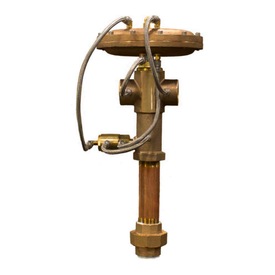
Summary of Contents for ThermOmegaTech THERM-O-MIX WWM
- Page 1 THERM-O-MIX WWM STATION ® Troubleshooting Manual www.ThermOmegaTech.com | 1-877-379-8258...
-
Page 2: Table Of Contents
Appendices Therm-O-Mix Safety Shower Station Schematic..............Therm-O-Mix Safety Shower Station Flow Chart..............Station Line Drawing...................... Therm-O-Mix WWM Safety Shower Station Checklist............WWM Diaphragm Actuator/V1 Mixing Valve Line Drawing............ WWM Diaphragm Actuator/V1 Mixing Valve Adjustment Photos........... V4 Control Valve Photo....................Page 1... -
Page 3: Introduction
• Phillips screwdriver Section 1.3: Check List Review the checklist below before troubleshooting the Therm-O-Mix WWM Safety Shower Station. See Appendix #4 for the printable checklist. • Does the plant have adequate Hot Water Flow Pressure? (Recommended min. 45 PSIG/ max. -
Page 4: Operating Sequence And Failure Modes
Section 2.0: Operating Sequence and Failure Modes Section 2.1: Normal Operating Sequence For Therm-O-Mix Station The V1 mixing valve blends the cold inlet water with the hot inlet water to produce the set-point outlet water temperature. If the water temperature out of V1 is high, V4 opens which short circuits the WWM Diaphragm Actuator reducing the hot water flow to the mixing valve outlet. -
Page 5: Troubleshooting
Section 3.0: Trouble Shooting and Repairs Section 3.1: Trouble Shooting/Repair Warning Statement Troubleshooting a Therm-O-Mix Station in the field may require turning off the hot and cold water supply to the emergency safety shower/eyewash system. As such, please contact the plant safety manager/supervisor and follow proper procedures for tagging, locking out, and other possible issues relating to servicing and temporarily rendering the safety equipment unusable. -
Page 6: Analyzing Component Failure By Conditions
Section 3.4: Analyzing Component Failure by Conditions CONDITION COMPONENT FAILURE Follow Section 3.1 & 3.2 to decommission the station for repair. Follow Section 4.2 to adjust the V1 Mixing Valve outside the unit. If the valve If the outlet temperature remains above the cannot be adjusted correctly a replacement WWM normal range for long periods of time Diaphragm Actuator is required. -
Page 7: V1 Mixing Valve Adjustment Instructions With The Wwm Diaphragm Removed
Section 4.2: V1 Mixing Valve Adjustment Instructions with the WWM Diaphragm Removed Before beginning repairs read and understand Section 3.1 and follow the steps in Section 3.2 to decommission the Therm-O-Mix Station. The Station should be tested after all repairs are completed. - Page 8 Section 4.3: V1 Mixing Valve Replacement Instructions Before beginning repairs read and understand Section 3.1 and follow the steps in Section 3.2 to decommission the Therm-O-Mix Station. The Station should be tested after all repairs are completed. 1. Label each hose connection going to the diaphragm housing for easy re-installation. (See Appendix #3) 2.
-
Page 9: V4 Control Valve Replacement Instructions
Section 4.4: V4 Control Valve Replacement Instructions Before beginning repairs read and understand Section 3.1 and follow the steps in Section 3.2 to decommission the Therm-O-Mix Station. The Station should be tested after all repairs are completed. V4 Control Valve Test 1. -
Page 10: Appendices
The Station checklist should be used whenever troubleshooting or repair work is done on a unit. The Station Serial Number is located on the V1 Mixing Body. The checklist can be sent to valves@thermomegatech.com or faxed to # 215-674-8594, Attn: Engineering, if any additional troubleshooting is required. -
Page 11: Therm-O-Mix Safety Shower Station Schematic
APPENDIX #1: Therm-O-Mix Safety Shower Station Schematic DIAPHRAGM SUPPLY HOSE DIAPHRAGM DRAIN HOSE DIAPHRAGM HEAD PORT PORT C HOT WATER COLD WATER INLET INLET 1" NPT 1" NPT FEMALE FEMALE V1 VALVE V4 VALVE V4 DRAIN HOSE COLD WATER TEPID WATER PORT A HOT WATER TEPID WATER... -
Page 12: Therm-O-Mix Safety Shower Station Flow Chart
APPENDIX #2: Therm-O-Mix Safety Shower Station Flow Chart START IS COLD V4 OPEN, WATER SUPPLY DIAPHRAGM ACT. ABOVE 95 F? OVERRIDE IS HOT WATER DIAPHRAGM ACT. AVAILIBLE? OVERRIDE MIXING VALVE (V1) BLENDS HOT & COLD WATER TO SET POINT MIXING VALVE V4 OPEN, OUTLET DIAPHRAGM ACT. -
Page 13: Station Line Drawing
APPENDIX #3: Station Line Drawing CAP NUT DIAPHRAGM HEAD PORT B HOT WATER INLET V1, MIXING VALVE 1" NPT FEMALE ORIFICE HOSE ASSEMBLY 7.5" PORT C COLD WATER INLET ORIFICE 1" NPT FEMALE ORIFICE HOSE ASSEMBLY 15" HOSE ASSEMBLY 9" HOSE ASSEMBLY 9"... - Page 14 APPENDIX #4: Therm-O-Mix WWM Safety Shower Station Checklist Company_________________________________ Contact___________________________________ Plant Location_____________________________ Phone____________________________________ Serviceman/Company_______________________ Date_____________________________________ Station/Serial Number_______________________ Unit Location______________________________ Does the plant have adequate hot water flow pressure? (Recommended min. 45 PSIG/ max. 100 PSIG________________ Is the stations hot water supply line properly sized? (Recommended min. 1” IPS)_______________ Does the plant have adequate cold water flow pressure? (Recommended min.
-
Page 15: Wwm Diaphragm Actuator/V1 Mixing Valve Line Drawing
APPENDIX #5: WWM Diaphragm Actuator/V1 Mixing Valve Line Drawing SET POINT +5 F SET POINT -5 F CAP NUT FOR ADJUSTMNET SET SCREW 1" HEX 1-1/2 HEX CARTRIDGE CAP .175 O-RING .160 SPOOL THERMOSTATIC ACTUATOR Page 14... - Page 16 APPENDIX #6: WWM Diaphragm Actuator/V1 Mixing Valve Adjustment Photo Loosen lock nut. Adjust calibration screw. Page 15...
- Page 17 WARNING: This product can expose you to chemicals, for example lead, nickel, acrylonitrile, which are known to the State of CA to cause cancer, birth defects, or reproductive harm. For more information, go to www.P65Warnings.ca.gov ThermOmegaTech®, Inc. 353 Ivyland Road 1-877-379-8258...

Need help?
Do you have a question about the THERM-O-MIX WWM and is the answer not in the manual?
Questions and answers