Table of Contents
Advertisement
Quick Links
Advertisement
Table of Contents

Related Manuals for Amfeltec Squid SKU-086-36


Summary of Contents for Amfeltec Squid SKU-086-36
- Page 1 About this Document Squid PCIe Gen 3 Carrier Board™ for six M.2 / NGSFF(NF1) SSD modules (SKU-086-36) Hardware Manual August 15, 2020 Revision 1.3 Squid PCIe Gen 3 Carrier Board™ for six M.2/NGSFF(NF1) SSD modules. Hardware Manual Revision 1.3 Page 1...
-
Page 2: Table Of Contents
About this Document Contents About this Document ........................4 Purpose ..........................4 Feedback ..........................4 Revision History ........................4 General Description .......................... 5 Introduction ........................... 5 Package Contents......................... 6 Features ............................8 Features ..........................8 PCI Express Carrier board for six M.2/NGSFF SSD modules block diagram...... 9 Installation ............................ - Page 3 About this Document Figures Figure 1: PCIe Gen 3 Carrier Board with six M.2 SSD modules (top and bottom sides) ........7 Figure 2: Carrier board internal block diagram..................9 Figure 3: PCIe Gen 3 Carrier Board for six M.2/NGSFF(NF1) modules - layout ..........13 Tables Table 1: PCIe Gen 3 Carrier Board for six M.2/NGSFF(NF1) modules - LEDs ..........
-
Page 4: About This Document
AMFELTEC Corp. makes every effort to ensure that the information contained in this document is accurate and complete at the time of release. Please contact Amfeltec if you find any errors, inconsistency or have trouble understanding any part of this document. -
Page 5: General Description
General Description General Description Introduction Squid PCI Express family is a series of PCIe Carrier Boards designed for desktop computers, servers, embedded appliances or storage expansion. Squid family expands a motherboard’s PCIe slot with multiple full/half-size MiniPCI Express or multiple M.2/NGSFF(NF1) PCI Express SSD modules. -
Page 6: Package Contents
General Description Package Contents PCIe Gen 3 Carrier Board package includes the following parts: PCIe Gen 3 Carrier Board for six M.2 / NGSFF(NF1) PCIe modules (Figure 1, 2) with x16 or x8 PCIe upstream Adapter Auxiliary 12V power cable SKU-043-39 (Appendix A, Figure 10) Set of Heat sinks for all six of M.2 / NGSFF (NF1) modules. -
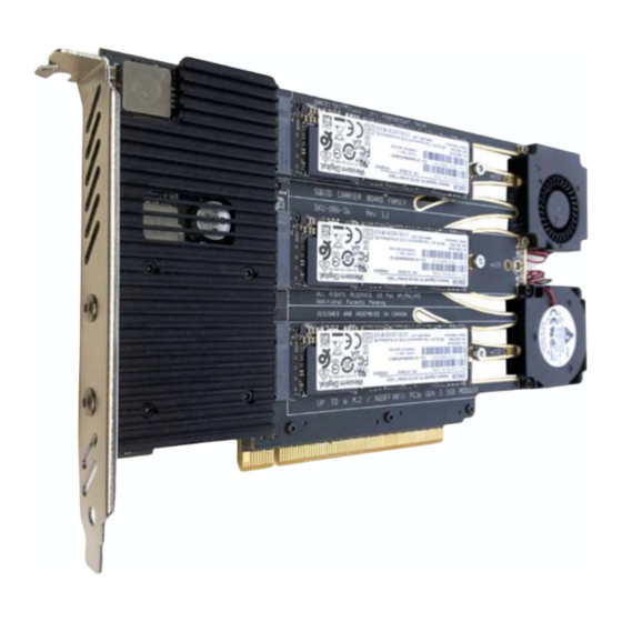
Page 7: Figure 1: Pcie Gen 3 Carrier Board With Six M.2 Ssd Modules (Top And Bottom Sides)
General Description Figure 1: PCIe Gen 3 Carrier Board with six M.2 SSD modules (top and bottom sides) Squid PCIe Gen 3 Carrier Board™ for six M.2/NGSFF(NF1) SSD modules. Hardware Manual Revision 1.3 Page 7... -
Page 8: Features
Features Features Features • Easy ‘Plug and Play” installation. No drivers needed. Transparent to the operation system. • Compatible to any motherboard. • Supports up to six M.2 or NGSFF(NF1) PCI Express SSD modules (M-key) • Supports any modules with 80 mm and 110 mm length, and up to 32 mm in width. •... -
Page 9: Pci Express Carrier Board For Six M.2/Ngsff Ssd Modules Block Diagram
Features PCI Express Carrier board for six M.2/NGSFF SSD modules block diagram. Figure 2: Carrier board internal block diagram. Squid PCIe Gen 3 Carrier Board™ for six M.2/NGSFF(NF1) SSD modules. Hardware Manual Revision 1.3 Page 9... -
Page 10: Installation
Installation Installation Carrier board installation Following steps provide the exact sequence that needs to be followed in order to properly install the Amfeltec PCIe Carrier Board: • Turn OFF computer before installation. • Remove the chassis cover from the computer. -
Page 11: Carrier Board Power Off. Backup Status Indication
Installation D14-D21 are solid OFF There is normal operation and all PCIe lanes are connected. Always off U10 module connection issue: connection with less than 4 PCIe lanes D15 on or connection speed is less than 8.0 Gbps. U9 module connection issue: connection with less than 4 PCIe lanes D16 on or connection speed is less than 8.0 Gbps. - Page 12 Installation The following status information is displayed on the status LEDs D14-D21 located on the bottom (soldering) side of the board after power is shut off: D14 blinking Backup status information is displayed on the D15-D21 LEDs. U10 module connection issue: connection with less than 4 PCIe lanes D15 on or connection speed is less than 8.0 Gbps.
-
Page 13: Hardware Description
Hardware Description Hardware Description Board Layout Figure 3: PCIe Gen 3 Carrier Board for six M.2/NGSFF(NF1) modules - layout Squid PCIe Gen 3 Carrier Board™ for six M.2/NGSFF(NF1) SSD modules. Hardware Manual Revision 1.3 Page 13... -
Page 14: Leds
Hardware Description LEDs Ref. Name Color Usage Des. RESET Global PCI Express RESET signal from motherboard STATUS YELLOW (Currently not used). UPSTREAM GREEN Upstream PCIe Link status. U5 M.2 circuit GREEN Downstream x4 PCI Express Gen 3 link status. U6 M.2 circuit GREEN Downstream x4 PCI Express Gen 3 link status. -
Page 15: Connectors
Hardware Description LEDs D3-D9 will indicate the follow status of the PCIe links: Solid OFF PCIe link is down Blinking at 1 Hz (512 ms OFF, 512 ms ON) PCIe link is UP at 2.5 GT/s (Gen 1) Blinking at 2 Hz (256 ms OFF, 256 ms ON) PCIe link is UP at 5 GT/s (Gen 2) Solid ON PCIe link is UP at 8 GT/s (Gen 3) -
Page 16: Cables
Appendix A: Appendix A: Cables Figure 4: SKU-043-37 USB terminal cable (optional). Figure 5: SKU-043-41 USB terminal cable (optional) Both SKU-043-37 and SKU-043-41 Terminal cables is using to support Real-time performance equires Silicon and temperature monitoring option via USB connection. This monitoring option r Labs CP2102 bridge driver installation https://www.silabs.com/products/development-tools/software/usb-to-uart-bridge-vcp-drivers Squid PCIe Gen 3 Carrier Board™... - Page 17 Appendix A: Figure 6: SKU-043-39 12V Auxiliary power cable (included) Auxiliary power can be taken from not-used x1, x4, x8 or x16 PCI Express slot by using SKU-043-39 power cable. Auxiliary cable has to be installed in case that total modules’ power consumption exceeds 55W (9.1 W per module) or NGSFF/NF1 SSD module installed! Figure 7: SKU-050-40 12V Auxiliary power cable (optional) Auxiliary power can be taken from standard 2x3 ATX psu connector by using SKU-050-40 power...
- Page 18 Appendix A: Squid PCIe Gen 3 Carrier Board™ for six M.2/NGSFF(NF1) SSD modules. Hardware Manual, Revision 1.3 Page 18...
-
Page 19: Appendix B: Limited Warranty
Amfeltec Corporation does not warrant that the operation of the hardware, software or firmware products will be uninterrupted or error free. Amfeltec products are not intended to be used as critical components in life support systems, aircraft, military systems or other systems whose failure to perform can reasonably be expected to cause significant injury to humans.
Need help?
Do you have a question about the Squid SKU-086-36 and is the answer not in the manual?
Questions and answers