
Related Manuals for Ametek Land SPOT

Summary of Contents for Ametek Land SPOT
- Page 1 SPOT INSTALLATION GUIDE PUBLICATION N 808274 LANGUAGE: ENGLISH WATER COOLED MOUNTINGS including Sealed to Process variant Q U A L I T Y C U S T O M E R S O L U T I O N S...
- Page 2 Observe precautions for handling electrostatic discharge sensitive devices. Equipment Operation Use of this instrument in a manner not specified by AMETEK Land may be hazardous. Read and understand the user documentation supplied before installing and operating the equipment. The safety of any system incorporating this equipment is the responsibility of the assembler.
- Page 3 This manual is provided as an aid to owners of AMETEK Land’s products and contains information proprietary to AMETEK Land. This manual may not, in whole or part, be copied, or reproduced without the expressed written consent of AMETEK Land.
-
Page 4: Table Of Contents
SPOT Water Cooled Mountings Contents Installation Dimensions Water Cooled Jacket Installation Dimensions Pan & Tilt Mounting Installation Dimensions Air & Water Specifications Maximum recommended limits Maximum ambient temperature Installing the SPOT Thermometer in the Water Cooled Mounting 3.1 Using an Analogue Cable... -
Page 5: Installation Dimensions
INSTALLATION DIMENSIONS... - Page 6 SPOT Water Cooled Mountings Installation Guide...
- Page 7 Water Cooled Mountings SPOT Installation Guide...
-
Page 8: Air & Water Specifications
AIR & WATER SPECIFICATIONS... -
Page 9: Maximum Recommended Limits
Water Cooled Mountings SPOT Air & Water Specifications 2.1 Maximum recommended limits Water pressure 6 bar Air pressure 3 bar Water flow rate 1 litre per min / 0.26 US gal per min Inlet water temperature 45 °C / 113 °F Outlet water temperature 50 °C / 122 °F... - Page 10 INSTALLATION...
-
Page 11: Installing The Spot Thermometer In The Water Cooled Mounting
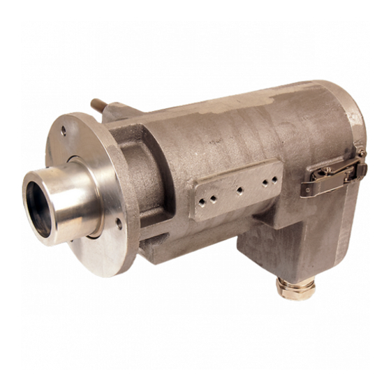
Water Cooled Mountings SPOT Installing the SPOT Thermometer in the Water Cooled Mounting Note The Water Cooled Mounting is supplied fitted with a cable gland for the Power over Ethernet (PoE) cable, and a Blanking Plug fitted in the Analogue Cable port. If you want to use an Analogue cable, you will need to replace the Blanking Plug with a Large Connector Sealed Gland (M25) (Land Part Nº 810481), available from Land Instruments International. Refer to Section 3.1 in addition to the following instructions. Fig. 3-1 shows a SPOT Thermometer, with Water Cooled Mounting and Power over Ethernet (PoE) cable. Fig. 3-1 Unclip the fastener on the Water Cooled Mounting and open the hinged Back Cap (Fig. 3-2). Fig. 3-2 Installation Guide... - Page 12 SPOT Water Cooled Mountings Insert the SPOT Thermometer into the Water Cooled Mounting and secure it in place with the Sprung retainer clip (Fig. 3-3). Sprung retainer clip Fig. 3-3 Unscrew the cable gland shell and split bush from the Water Cooled Mounting. Slide the PoE Cable through the gland shell and fit the split bush between the gland shell and Fig. 3-4 the connector (Fig. 3-4). Slide the PoE Cable through the cable gland and attach it to the Thermometer connector (Fig. 3-5).
-
Page 13: Using An Analogue Cable
Water Cooled Mountings SPOT 3.1 Using an Analogue Cable For the Analogue Cable, unscrew the Blanking Plug from the Water Cooled Mounting. Disassemble the M25 Cable Gland. Note: The Hexagonal Locknut is not required for this installation. Slide the Analogue Cable Fig. 3-7 connector through the gland outer shell and the seal washer (Fig. 3-7). Fit the split bush between the washer and the main body of the gland. Insert the Analogue Cable into the connector on the rear of the thermometer. Tighten the cable gland into the body of the thermometer. Close the hinged Back Cap and secure it in place with the fastener (Fig. 3-6). The Thermometer is now installed in the Water Cooled Mounting. Installation Guide... - Page 14 Blank...
- Page 15 Blank...
- Page 16 For a full list of international offices, please visit our website www.ametek-land.com Copyright © 2019 LAND Instruments International. Continuous product development may make it necessary to change these details without notice. SPOT Water Cooled Mountings Installation Guide, Issue 6, 05 March 2019...
Need help?
Do you have a question about the SPOT and is the answer not in the manual?
Questions and answers