Advertisement
This manual provides General Information, Installation, Operation, Maintenance and System Set-Up Information for METRON Model
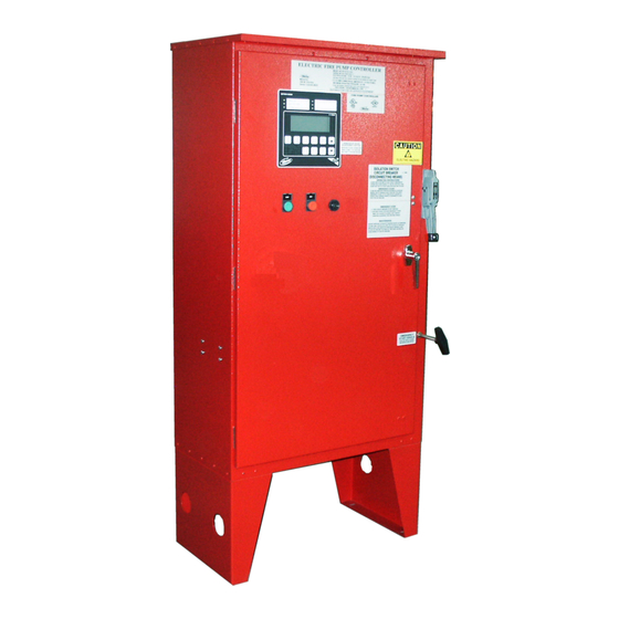
Model MP300 through MP700 Electric Motor Driven Fire Pump Controllers.
APPENDIX 1
Changing Printer Paper and Ribbon Cartridge..........................................................................................PAGE 23
18 Autumn Park, Dysart Road, Grantham, LINCS. NG31 7DD. United Kingdom
Telephone: +44 (0) 1476 516120
Metron, Inc.
Revision: B
MANUAL FOR MODEL MP300 to MP700
ELECTRIC MOTOR DRIVEN
FIRE PUMP CONTROLLERS
Starting Serial No. "MA"
TABLE OF CONTENTS
METRON ELEDYNE LIMITED
FAX: +44 (0) 1476 516121 email:
www.metroneledyne.co.uk
METRON, INC.
1505 West Third Avenue
Denver, Colorado 80223
www.metroninc.com
Telephone: (303) 592-1903 Fax: (303) 534-1947
Date:
09/22/04
Date:
06/14/06
info@metroneledyne.co.uk
Approved:
MH
Approved:
MH
DOC#:
605
Page:
1 of 24
Advertisement

Summary of Contents for Metron Eledyne MP300
-
Page 1: Table Of Contents
FIRE PUMP CONTROLLERS Starting Serial No. "MA" This manual provides General Information, Installation, Operation, Maintenance and System Set-Up Information for METRON Model Model MP300 through MP700 Electric Motor Driven Fire Pump Controllers. TABLE OF CONTENTS PART I General Information.............................PAGE 3 PART II Functions..............................PAGE 3... - Page 2 THIS PAGE IS BLANK Page 2 of 24...
-
Page 3: Part I General Information
PART I: GENERAL INFORMATION The basic function of the model MP Fire Pump Controller for electric motor driven fire pumps is to automatically start the fire pump electric motor upon a drop in pressure in the water main, or from a number of other demand signals. This controller provides alarm and/or alarm shutdown protection for various motor and power failures. -
Page 4: Part Iii Operation Of The Controller
PART III: OPERATION OF THE CONTROLLER A. When the controller is in the "Auto" mode, the main circuit breaker and isolation switch are in the "On" position, the controller is in standby condition ready to start the pump automatically. A green pilot light above the "Auto" button will illuminate in this mode. -
Page 5: Part Iv Installation & Test Procedure
G. Series MP420 Part-Winding Start: There are two contactors for part-winding start. The start contactor will close immediately on demand and the other will close after a preset transition time delay (See Screen #314). Full voltage will be present at the output of both contactors. - Page 6 INPUT/OUTPUT STATUS INDICATOR LIGHTS Light Emitting Diodes (L.E.D.) lights have been installed on the microprocessor module to indicate the status of each input and output terminal. Status indication for the standard functions is given below: Terminal Number L.E.D. (light) "ON" Indication (Microprocessor Func #) (Out 02) Circuit Breaker Shunt Trip...
-
Page 7: Part V Operator Interface Device (Oid) Use And Navigation
AN ADJUSTABLE SEQUENTIAL START TIMER IS SUPPLIED FOR MULTIPLE PUMP INSTALLATION: Normally, the leading pump Controller will not have a delay timer and will commence starting of the pump immediately upon operation of a demand signal (other than Power Failure which is time delayed). The subsequent Controllers will have a time delay which is adjustable from 0 to 999 seconds. - Page 8 OID Screen Map METRON OID100 POWER SYSTEM SYSTEM CHANGE/ CONFIG PRINT STATUS LOGS ENTER SILENCE/ AUTO MANUAL TEST RESET/ SYSTEM STATUS B1 SYSTEM LOGS CONFIG PRES STRT AB 460V 1) Alarm Log 1) SYSTEM SETPOINTS BC 461V 2) Event Log 2) USER PREFERENCES AC 460V 3) Pressure Log...
- Page 9 Analog Input 01 AUX# 1 Pressure Time Clock Number Slope: Enabled [100.0]psi 0-999.9 [17:03:52] [ MP300] [0.2135677] [Yes] 102 SYSTEM SETPOINTS 202 USER PREFERENCES 302 TECH SCREENS 401 ANALOG SIGNALS 502 AUX USER PROGRAM Pump Stop Set System Date Transfer Switch...
- Page 10 116 SYSTEM SETPOINTS 216 USER PREFERENCES 316 TECH SCREENS 415 ANALOG SIGNALS Supervisory Power Low Discharge Single Phase Loss Phase BC Voltage Failure Startup Alarm Pressure Time Delay Slope: [Yes] [100] 0-999 [5]seconds 0-99 [0.12430] 117 SYSTEM SETPOINTS 217 USER PREFERENCES 317 TECH SCREENS 416 ANALOG SIGNALS Supv.
- Page 11 Controller Power Controller Model scrolling through the Alarm, Event, and On Time 18.5 Hrs Number Pressure Logs 10/15/04 17:53:26 [MP300] SYSTEM STATUS Firmware Ver SV 1.1 Commissioned Date: 11/15/02 401 ANALOG SIGNALS Analog Input 01 Slope: [0.21346771] 501 AUX USER PROGRAMS...
- Page 12 SYSTEM LOGS: The Model MP Electric controller has three separate data logs; 1) alarm log, 2) event log, and 3) pressure log. The alarm log is a subset of the event log and only displays the last ten alarms that have occurred or cleared. The event log records all alarm and system function type events SYSTEM LOGS: The [UP] and [DOWN] arrow buttons can be used to scroll through the SYSTEM LOGS...
- Page 13 Printing System Log Data: The following applies if a printer has been installed or a PC is connected to the RS232, RS485 or USB com ports using the appropriate cable. When the [PRINT] button is pressed when looking at data in one of the three logs, a menu for what is to be printed is displayed.
- Page 14 CONFIGURATION SCREENS: All parameters that control the operation of the controller can be viewed and changed within the Configuration set point screens. Each set point is protected by a user password to prevent unauthorized changes. The system set points are separated into five different group CONFIG 1) SYSTEM SETPOINTS (Level 1 password): These setpoints adjust the conditions 1) SYSTEM SETPOINTS...
- Page 15 Printing Configuration Setpoints: The following applies if a printer has been installed or a PC is connected to the RS232 com port using a null modem cable. When the [PRINT] button is pressed while looking at a configuration setpoint screen, a menu for what is to be printed is displayed.
-
Page 16: Part Vi System Set Point Definitions
PART VI: SYSTEM SET POINT DEFINITIONS Configure System Setpoints If system pressure is at or below this setting the pump will start if the system is in 101 SYSTEM SETPOINTS Pump Start Auto mode. Pressure [ 60] psi 0-999 102 SYSTEM SETPOINTS If system pressure is at or above this setting and the pump is running in Auto Pump Stop mode, the pump can be stopped using the stop pushbutton or can automatically... - Page 17 The length of time the pump will run when started on automatic weekly test. Must 112 SYSTEM SETPOINTS Auto Weekly Test Length be set for a minimum of 10 minutes per NFPA 20.. of Run Time [ 10] minutes 0-99 113 SYSTEM SETPOINTS When this feature is enabled, the controller will stop the pump during the Stop Motor Duing Test...
- Page 18 If enabled this setting activates the logic to monitor an optional deluge valve dry 124 SYSTEM SETPOINTS Deluge Valve contact opening (ie normally closed contact that opens to start pump) that will start Pump Start the pump if system is in Auto mode. [No ] Page 18 of 24...
- Page 19 Configure User Preferences 201 USER PREFERENCES Set the current controller clock (24 hour clock). Set System Real Time Clock [17:03:52] Set the current controller date. 202 USER PREFERENCES Set System Date [12/31/99] Set the local day of the week. 203 USER PREFERENCES Set System Day Of The Week [Monday...
- Page 20 Configure User Preferences (continued) 213 USER PREFERENCES The pressure at or above which will cause a High Pressure alarm condition High Discharge Pressure Alarm Pressure [185] psi 0-999 214 USER PREFERENCES The amount of time the pressure must be at or above the set pressure before the High Discharge Alarm alarm condition is activated.
-
Page 21: Part Vii Alarm And Event Log Messages
PART VIII: ALARM AND EVENT LOG MESSAGES The following is a sample of the possible messages that could be recorded within either the alarm or event logs. Phase Failure Phase Failure declared when all three phases of the incoming power is present not Alarm Occurred/ within the limits set in the configuration screens. - Page 22 Aux Alarm Text List Messages List of possible internal variables used as inputs for aux alarm user programs. Auxiliary Alarm Low Pump Room Temp Pump Running Reservoir Low Power Available Reservoir Empty Phase Reversal Reservoir High Motor Overload Flow Meter On Remote Start Relief Valve Open Local Start...
- Page 23 rest of the roll. Remove any damaged or APPENDIX 1 - PRINTER OPERATION gummed part of the paper, and cut the free end squarely with a pair of scissors or a knife, leaving Operator Information a clean straight edge to present to the printer There are two buttons on the front panel of the mechanism.
- Page 24 Open the printer door by pressing the door latch Ensure that the ribbon is taut and parallel to the inwards. paper. Place forefinger against the lower edge of the If necessary tighten the ribbon by turning the mechanism mounting chassis and thumb against faceted disc clockwise using fingernail (see the base of the door (see Figure 6).
Need help?
Do you have a question about the MP300 and is the answer not in the manual?
Questions and answers