
Summary of Contents for STS 808
- Page 1 Labeling machine for spreading labels on cylindrical surfaces LABEL APPLICATOR STS 808 Operating manual /original instruction/ V.4.02 phone: (+359) 66 801 536 fax: (+359) 801 547 info@stselectronics.eu www.stselectronics.eu...
-
Page 3: Table Of Contents
Content Pictograms used................... page 3 1. Introduction...................... page 3 Proper use....................page 4 Equipment ....................page 5 Scope of delivery ..................page 5 Technical data .................... page 5 Noise information..................page 5 2. General safety instructions for handling electrical appliances. Safe work .................... -
Page 4: Pictograms Used
In the present Operation Manual have been used the following pictograms. Read the Operation Manual! Follow safety warnings and instructions! Protect yourself from electric shock. Danger to life! Keep the children away from the machine! Risk of life from electric shock when a power cord or plug is damaged! Dispose the packaging and the appliance in accordance with environmental regulations! 1. -
Page 5: Proper Use
Proper usage The machine is designed to spread one or two self-adhesive labels (front side and back side ones) on cylindrical vessels of different diameter and length, with smooth walls. Labels should be on one roll, / in case of front and back labels - arranged consequently in series / on the conveyor. -
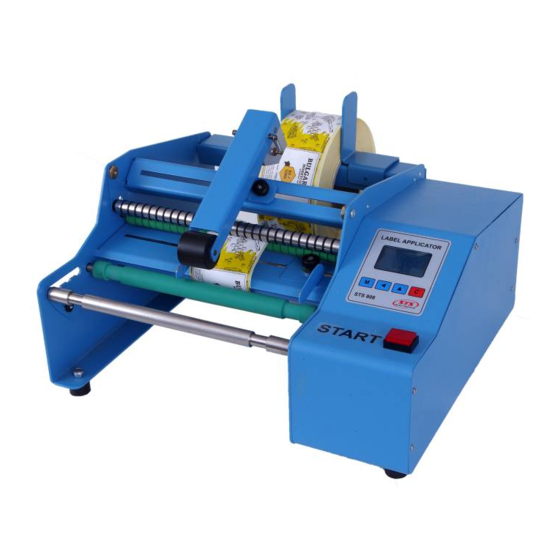
Page 6: Equipment
Equipment /Figure 1.1, Figure 1.2/. 1. Supporting shaft. 10. Control panel. 2. Driving shaft. 11. Start button. 3. Stopers (detents). 12. Sensor for labels. 4. Pull shaft. 13. Power switch. 5. Pressing shaft. 14. Power supply coupling. 6. Clamping mechanism 15. - Page 7 Peeling edge Figure 1.1 Figure 1.2 - 6 - V.4.02 STS808 phone: (+359) 66 801 536 fax: (+359) 801 547 info@stselectronics.eu www.stselectronics.eu...
-
Page 8: General Safety Instructions For Handling Electrical Appliances
2. General safety instructions for handling electrical appliances. Attention! The following safety precautions must be observed when using electrical appliances to protect against electric shock, risk of injury and fire. Read all of these instructions before using the machine and store them carefully. -
Page 9: Operating Instructions
3. Operating instructions Attention ! Every operator working wth the labeling machine (with the Label aplicator) should become acquainted carefully with the present operating manual. Mounting. The machine should be placed on a flat, horizontal surface larger than its base. Should provide space around the machine for maintenance servicing and handling. From the kit supplied with it, a power cord is conected to the supply socket and alsow a 'start pedal' is connected to an external start cuplung. -
Page 10: Turn On
is caried out according to Appendix 1. The beginning of the label (front - for two labels) is positioned next to the peeling edge. The pressure shaft is 'locked'. Label tape drivers are positioned and fixed to the edges without squeezing it. Turn on. -
Page 11: Appendix 1 - Setting Up The Label Sensor
Appendix 1 - Ajustment of the label sensor. The sensor is positioned in such a way that the label and the support base must completely cover the sensor area (narrow gap) when moving. In the case of irregularly shaped labels, cut- off parts must not pass through the sensor area. -
Page 12: Appendix 2 - Determination Of Parameter Value - Offset Stop
Appendix 2 Determination of parameter value Offset stop. Determines the right positioning of the begining end of the following (subsequent label) to the peeling edge. There are some possible variants and they are shown on Figure 3.4 L = 100mm - distance between the label Offset stop = 100mm sensor and the peeling edge. -
Page 13: Appendix 3 - Determination Of Parameter Value - Offset Stop
Appendix 3 Determination the parameter value of Offset stop 1 Offset stop 1 determines the correct positioning of the begining end of following (subsequent) back label against to the peeling edge. Measerment shall be done from the begining end of back label. There are several possible variants and are shown in Figure 3.5 L = 100mm - distance between the label Offset stop 1 = 100mm... -
Page 14: Determination Of Parameter Value - Offset Stop
Determination of the parameter value - Offset stop 2. Offset stop 2 determines the right (the correct) position of the begining of the following (subsequent) front label to the peeling edge. Measerment shall be done from the beginnig of the front label. There are some possible variants and they are shown in Figure 3.6. -
Page 15: Appendix 4 - Working With The Menu And Setting Parameters
Appendix 4 - Working with the menu and changing parameters. Access to the parameter change menu is password protected. MODE 1 LABEL Pressing and holding the key for longer than 3 seconds displays a ------------------------------ WAIT START password window - Figure 3.8. It is canceled by pressing the key, and access to the input menu by pressing the key - Figure 3.9. - Page 16 By pressing the key, the reading is reset. By pressing the OFFSET STOP key, the set offset is confirmed and proceeds to setting the next parameter - ------------------------------ movement time - Figure.3.15. The value determines the time of rotation of the vessel in order to adhere the label.
- Page 17 digit shall be done by pressing the key. The process is cyclical. By TIME MOVE MOTOR pressing key the reading is reset. By pressing key, the set ------------------------------ 02.00 Offset stop 2 is confirmed and proceeds to the setting of the next parameter - movement time - Figue 3.21.
-
Page 18: Appendix 5 - Adjusting The Brightness And The Contrast Of The Display
Appendix 5 - Ajustment of the brightnes and the contrast of the display. The menu for changing the display settings is accessed from the MODE 1 LABEL ------------------------------ operating mode - Figure 3.22. WAIT START Pressing and holding for longer than 3 seconds on the key will enter the contrast adjustment mode - Figure 3.23. -
Page 19: Appendix 6 - Determination Of Parameter Value - Distance Between Labels
Appendix 6 Determination of the parameter value - Distance beween the labels Vessel (container) /bottle, jar/ Back label Front label length of length of front label back label distance between labels L1 - length of front label [mm] L2 - length of back label [mm] L3 -distance between front and back label [сm] D - diameter of the vessel /container/ [mm] L3 = ( ( D*3,14 - L1 - L2 ) / 2 ) /10... -
Page 20: Maintenance And Cleaning
4. Maintenace and cleaning Attention! Risk of injury! Always disconnect the plug from the socket before performing any work on the machine. The labeling machine does not require any technical maintenance within the specified service life. Clean the machine after finishing the job. Use a brush or a dry cloth. -
Page 21: General Terms
6. Waranty General conditions The machine is manufactured with due care and tested in good faith. It is intended for use in normal climatic conditions, in an environment with normal fire safety, without liquids and gases aggressive to the housing material. In case of a warranty event, contact a certified service center. -
Page 22: Ec Declaration Of Conformity
Declares under its own responsibility that the STS 808 labeling machine complies with the requirements of: DIRECTIVE 2006/42 / EC, introduced by the Ordinance on Essential Requirements and Conformity Assessment of Machines DIRECTIVE 2014/30 / EC, introduced by the Ordinance on Essential Requirements and Conformity Assessment for Electromagnetic Compatibility. -
Page 24: Producer
10. Producer STS Еlectronics Ltd. City of Gabrovo 5300 14 „Stancionna“ street FACTORY NUMBER:_______________________________________ V.4.02 STS808 phone: (+359) 66 801 536 fax: (+359) 801 547 info@stselectronics.eu www.stselectronics.eu...
Need help?
Do you have a question about the 808 and is the answer not in the manual?
Questions and answers