
Subscribe to Our Youtube Channel
Related Manuals for Glamox Aqua Signal NL90


Summary of Contents for Glamox Aqua Signal NL90
- Page 1 NL90 Touch Screen Navigational Light Controller User manual Rev.: 1, Print date: 2016-06-17...
-
Page 2: Technical Specification
Contens: 1. Overview 1.1 Description 1.2 Design 1.3 Package cotents 1.4 Build-up procedure 2. Safety instructions 3. Installation 3.1 Installation requirements 3.1.1 Arrangement 3.1.2 Connection 3.1.3 Factory configuration/connection 3.2 Preparation 3.3 Mounting 3.3.1 Mounting of main unit 3.3.2 Mounting of power supply and input modules 3.4 Connecting 3.4.1 Connecting protective earth 3.4.2 Interconnecting modules... - Page 3 1. Overview 1.1 Description NL90 Touch screen Navigational Light Controller NL-90 is used to control the operation of navigation and signal lights on board ships. Its modular construction makes it suitable for any ship size. Color graphic LCD display with touch panel provides user-friendly interface which is very easy to operate.
- Page 4 ITNSL-01 comprises of 3 main parts: - Main unit - Power supply unit - Input modules Main unit Provides user interface for complete system, monitors operation of power supply and input modules. In case of failure detection alarms operator. Main unit contains complete configuration of lights as well as information of modules connected to it.
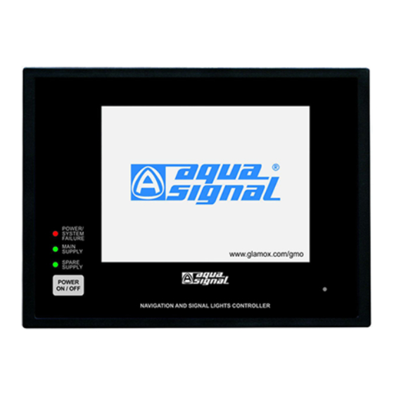
- Page 5 1.2 Design Main unit POWER/ SYSTEM FAILURE MAIN SUPPLY www.glamox.com/gmo SPARE SUPPLY POWER ON / OFF Touch screen display Buzzer Power/system failure indication LED Rating plate Main power supply indication LED Holders for fixing cables Spare power supply indication LED...
-
Page 6: Power Supply Module
Power supply module RJ45 connector for input module connection Input fuse for main power supply Input fuse for spare power supply Module label Terminals for NMEA 0183 communication Output for input module power supply TS35 rail for mounting Earth wire Input/output terminals for alarms DB9 connectors for main unit connection Input module... -
Page 7: Build Up Procedure
1.3 Package contents Following components are included in product package. Code Figure / name 02-04-019 POWER/ SYSTEM FAILURE MAIN SUPPLY www.glamox.com/gmo SPARE SUPPLY POWER ON / OFF Mounting clamps Main unit type ITNSL-01T Manual (4 pcs) 02-04-020 02-04-021 Original cable DB9 2,5m long for... -
Page 8: Safety Instructions
Use of non appropriate lights could lead to irregular operation of Navigation and signal lights controller and navigation lights which could indanger safe navigation of the ship. Special precautions need to be taken to check the compatibility of non-bulb and non-Glamox LED lights. -
Page 9: Navigation Lights
3. Installation 3.1 Installation requirements 3.1.1 Arrangement Before installation it is required that project specific drawing are made. This drawings must include connection drawings and lights arrangement drawings. In order to make drawings following information needs to be available: - name of lamps - color of lamps - position of lamps - type of lamps (double or single) - Page 10 3.1.2 Connection Interconncetions between modules INPUT MODULE FOR NEXT All original cables are cables for communication and 7 or 13 SIGNAL LIGHTS, have to be routed in accordance with rules and good marine practice. Have to be seperated from power ITSL-7 or ITSL-13 (link M1 removed*) cables which can cause high level of interference.
- Page 11 3.1.3 Factory configuration/connection Interconncetions between modules All original cables are cables for communication and have to be routed in accordance with rules and good marine practice. Have to be seperated from power cables which can cause high level of interference. INPUT MODULE FOR FIRST 13 SIGNAL LIGHTS, ITSL-13 (link M1 inserted)*...
- Page 12 3.2 Preparations Check the package contents Check the package content for visible signs of transport damage and for completeness. Damaged parts Do not install parts damaged during the shipment. In case of damaged parts, contact your supplier. Keep the supplied documentation and configuration form in a safe place. The documents belongs to the Navigation and signal lights controller and they are required for subsequent commissioning.
- Page 13 Arrangement Following arrangement of input modules needs to be followed. If module is not exsisting just skip it. ITNL-10 ITNL-3 1st ITSL (ITSL-13 or ITSL-7) 2nd ITSL (ITSL-13 or ITSL-7) Input module ITSL address selection ITNL-10 and ITNL-3 modules have fixed addresses while ITSL addresses need to be set via link M1. The first ITSL module must have link M1 inserted while the second ITSL module must have link M1 removed.
- Page 14 3.3 Mounting 3.3.1 Mounting of main unit Make cut-out according drawing bellow (1) and put main unit into cut-out (2). PANEL CUT-OUT 3. For mounting main unit to console 4 pcs of mounting clamps are provided (pls. check photo) Mounting clamps Clasp pin console 4.
- Page 15 3.4 Connecting Keep following sequence of tasks when connecting navigation and signal lights panel: 1. Connecting the protective earth 2. Interconnecting all modules 3. Connecting lamps’ circuits 4. Connecting power supply 5. Connecting input/output contacts and communication Strain relief!!! Contacts can be broken or wires can be torn off if cables are not provided adequate strain relief. Pls. provide adequate strain relief for all cables.
- Page 16 Fix the cables with cable strips. Do not overstress the connectors. Minimum bending radius is 40mm. Connecting power supply with the input modules For connecting power supply module with input modules RJ45 cables are provided. Follow the instructions bellow. 50 5152 53 50 5152 53 NEXT UNIT...
-
Page 17: Connecting Power Supply
3.4.4 Connecting power supply Before connecting check power supply rating as well as power supply unit voltage rating. Power suppy for navigation and signal lights controller are to be connected according prepared connection drawings. Power supply wires / ables need to be in accordance with systems’ power consumption. Connect cable sheild to equipotential bonding circuit. - Page 18 3.4.4 NMEA communication protocol: NMEA 0183 RECEIVER SENTENCE: When NMEA sentence $IIACK,000*55<CR><LF> is received, external audio alarm is accepted. NMEA 0183 TRANSMITTER SENTENCES: If there is no external alarm, NMEA sentence $IIALR,,,V,V,*73<CR><LF> is sent. If external alarm occures, NMEA sentence $IIALR,,,A,V,*64<CR><LF> is sent. If external alarm is accepted, NMEA sentence $IIALR,,,A,A,*73<CR><LF>...
-
Page 19: Enter Configuration Mode
1 Push and hold POWER ON/OFF push button Main supply (or spare supply) lights on Release POWER ON/OFF push button POWER/ SYSTEM FAILURE MAIN SUPPLY www.glamox.com/gmo SPARE SUPPLY After approx. 30s logo will appear POWER ON / OFF 1 Push 3 Release When “PREPARING START”... - Page 20 4.3 Navigation lights configuration mode Navigation lights configuration mode main screen Configured lights list with: - light number - light name - spare exist (if this text occurs double light is configured) Light position and color - colored circles present configured lights - grey circuit present possible position of light - selected light is blinking Property buttons for changing properties of selected light...
- Page 21 Custom name 1. Use keyboard to enter name. The letters may be inscribed until they fill the white field. 2. Tap on RETURN on the keyboard to exit and save. 3. Moving the keyboard along the screen is alowed by draging keyboard title bar.
- Page 22 Exit navigation light configuration 1. Tap on SIGNAL LIGHTS to enter signal lights configuration. 2. Tap on EXIT to save configuration and exit. Automatic reset will be done. Tab OK to continue. Check message!!! In case that configuration has been changed it is necessary to check lights grouping and connection before exiting configuration screen.
- Page 23 Configuration of lights name, number, position, grouping and connection is same as for navigational lights. For instructions pls. consult section 4.3 of this manual. Tap on property button MAST to change mast outines as well as PORT/ STBD side Markinks. 1.
-
Page 24: Turning Off
1 Push and hold POWER ON/OFF push button Main supply (or spare supply) lights on Release POWER ON/OFF push button POWER/ SYSTEM FAILURE MAIN SUPPLY www.glamox.com/gmo SPARE SUPPLY After approx. 30s logo will appear POWER ON / OFF 1 Push 3 Release NOTE: If power supply is not present during turning on POWER/SYSTEM FAILURE alarm will be released. -
Page 25: Normal Operation Mode
5.1 Normal operation mode Normal operation mode Main screen Navigational lights names, number and spare lantern availability/use SPARE EXISTS - spare lights is configured SPARE IN USE - spare light is turned on Navigational lights status: Turned on Alarm Failure Signal ligths names and number Navigation lights Signal lights... - Page 26 Light turning on / off For turning on/off, tap on appropriate lamp circle icon. 2. To turn on group, tap on group button 3. To turn off all lights, tap on ALL OFF Once finished tap on OK to confirm and exit to main screen. Main / Spare selection 1.
- Page 27 Broken light alarm presentation and alarm accepting Navigation and signal lights controller with built-in fault control continuously monitors status of navigation and signal lights. FAULT CONTROL In case of failure detection (1) it alarms operator (2). FAULT CONTROL Fault detection alarm 1.Alarm symbol, accept push button occurs and buzzer sounds.
-
Page 28: Manual Operation Mode
5.2 Manual operation mode Manual operation mode enables user to manualy turn on/off lights in case of emergency. Lights can be turn on/off by slide switches on the input modules. In case of manual operation power supply will be directly forwarded to lights bypassing all electronics. -
Page 29: Warning Messages
5.3 Warning messages All notices, warnings and errors will be displayd on message screen to provide operator information regarding current system status. Message screen Message box - message text is indicated by red text Accept button - button for confirming alarm Note! Given the importance of the event the message screen can: - disappear automatically... - Page 30 - FIRST NAVIGATION LIGHTS* MODULE IS NOT RESPONDING. MODULES NOT RESPONDING WILL BE UNREGISTERED FROM THE SYSTEM * or some other module If input module didn't respond during normal operation, but responds during next equipment turning on process, equipment proceeds with normal operation.
- Page 31 - PROBLEM IN COMMUNICATION OR FIRST NAVIGATION* LIGHTS MODULE MALFUNCTION IS DETECTED. CHECK LIGHTS! * or some other module IF YELLOW BACKGROUND LASTS LONG, SWITCH LIGHTS BY SWITCHES ON THE MODULE. This message appears in case when communication between main unit and input module exists, but with very often errors making it unreliable.
- Page 32 6. Commissioning 6.1 Commissioning procedure Required information: For starting up procedure it is required to have following information: - name of lamps - color of lamps - position of lamps - type of lamps (double or single) - power supply of lamps Steps: 1.
- Page 33 6.2 Configuration setup form AFTER FINISHING CONFIGURATION FILL IN THIS FORM!! Name Color* In order to back-up configuration it is necessary to fill in this form. Beside configuration of lamps it is necessary to fill in assigment of lamps to input modules and their terminals. Name Spare Color*...
-
Page 34: Technical Characteristics
7. Technical characteristics 1. Power supply............230V AC or 115V AC, depending on version connections for main and spare, automatic change- over, supply change-over signalling 2. Consumption (without lights) ....... 230V AC version - 0.135A max 115V AC version – 0.27A max 3. -
Page 35: Unit Outlines
13. Programmable lights’ presentation properties ..Colours: white, green, red, blue, yellow Numbers: 1-99, the same numbers are allowed Light’s position on display Signal mast shape Port-Stbd marking Lights name: Anchor Fwd, Mast Forward, Port, Starboard, N.U.C. Upper, N.U.C. Lower, R.A.M., Mast After, Stern, Anchor After, Suez Red, Suez White, Suez Green, Suez Blue, Suez Stern, Suez Fore, Kiel Canal, Dang. - Page 36 Power supply module FIXING HOLES NAVIGATION AND SIGNAL LIGHTS EQUIPMENT - POWER SUPPLY MODULE ITNSLP-01 POWER SUPPLY WEIGHT CODE MODULE (kg) ITNSLP-01, 230V AC 02-04-020 ITNSLP-01, 115V AC 02-04-021 Input modules HEIGHT NAVIGATION AND SIGNAL LIGHTS INPUT MODULES FIXING HOLES CONNECTION TERMINALS AND RJ45 CONNECTORS DIMENSION A...
-
Page 37: Troubleshooting
8. Troubleshooting In order to detect problem and solve it please follow these instructions. In case that your problem is not described, contact your sales representative for assistance. For easier check up of system front cover of power supply module can be removed. Pls. check bellow overview of power supply module PCB. - Page 38 1. Check Green LED on power supply module - 19 VDC for input module power supply (4). A) In case of one module not responding 2. Check fuse on input module and replace it 3. Restart system (turn system off and then on) If module is still not responding disconnect module from system according to instructions bellow.
- Page 39 Light failure ITNSL detects light faiulre by monitoring current lights circuit. When current drops bellow limit it acctivates alarm. Important!!! Even though lamp failure is indicated power supply can be still present on terminals. Switch off light on main unit and check if power supply is present on light circuit. 1.
- Page 40 9. APPENDIX Project information form Fill-in commisioning and project information given bellow and send it back to manufacturer. Steps: 1. Navigation lights controller is installed and connected according manual 2. Turn on power supply and turn on main unit. 3. Check if configuration on controller is in accordance with information regarding lights. 4.
- Page 41 Configuration setup form AFTER FINISHING CONFIGURATION FILL IN THIS FORM!! Name Color* In order to back-up configuration it is necessary to fill in this form. Beside configuration of lamps it is necessary to fill in assigment of lamps to input modules and their terminals. Name Spare Color*...
- Page 42 Germany Canada Singapore Glamox Aqua Signal GmbH Glamox Canada Inc. Glamox Far East Pte. Ltd Bremen Tel +1 709 753 2373 Tel +65 6748 1977 Tel +49 421 48 93-0 Fax +1 709 753 2180 Fax +65 6742 9711 Fax +49 421 48 93-210 sales@glamox.ca...
Need help?
Do you have a question about the Aqua Signal NL90 and is the answer not in the manual?
Questions and answers