
Related Manuals for Superior Electric SLO-SYN TD Series

Summary of Contents for Superior Electric SLO-SYN TD Series
- Page 1 sales@artisantg.com artisantg.com (217) 352-9330 | Click HERE Find the Warner Electric SLO-SYN TDC330/08 at our website:...
- Page 2 PRICE:$12.50 INSTRUCTIONS SUPERIOR SLO-SYN TD SERIES BRUSHLESS SERVO DRIVES Artisan Technology Group - Quality Instrumentation ... Guaranteed | (888) 88-SOURCE | www.artisantg.com...
- Page 3 Caution ENGINEERING CHANGES Superior Electric reserves the right to make engineering refinements on all its products. Such refinements may affect information given in instructions, Therefore, USE ONLY THE INSTRUCTIONS THAT ARE PACKED WITH THE PRODUCT.
-
Page 4: Table Of Contents
Table Of Contents SECTIONS & TITLE PAGE Things to Know Before Using This Equipment 1.0 - Introduction 1.1 - Using This Manual 1.2 - Product Features 2.0 - Specifications 2.1 - Mechanical and Environmental Specifications 2.2 - Electrical Specifications 2.3 - Signal Specifications 2.4 - LED Specifications 2.5 - Current Specifications 2.6 - Motor Specifications... - Page 5 THINGS TO KNOW BEFORE GETTING STARTED • Only qualified personnel should install or perform service on this equipment. Do not operate the unit without the enclosure as voltage present in this unit can cause serious or fatal injuries. • Before performing any work on this unit or the wiring, allow at least 5 minutes for the capacitors to fully discharge, to prevent electrical shock hazards.
-
Page 6: Introduction
1.0 INTRODUCTION 1.1 Using This Manual It is important that you understand how TD330 units operate before installing and using these products. We strongly recommend that you read this manual completely before proceeding with the installation. This manual is an installation and operating guide for the TD330/04 and the TD330/08 Torque Mode Amplifiers (Drives). -
Page 7: Specifications
2.0 SPECIFICATIONS 2.1 Mechanical and Environmental Specifications Size: 2.88W x 10.63H x 8.07D (See Figure 3.1) Weight: TD330/04: 6.75 lbs. TD330/08: 7.25 lbs. Temperature: 0°C to 50°C (32°F to 122°F) operating -40°C to 75°C (-40°F to 167°F) storage Max. Heatsink Temp: 70°C (158°F);... -
Page 8: Signal Specifications
2.3 Signal Specifications +5V and +5V COM : 5Vdc, 0.3 amps power supply to be used for hall and/or encoder devices. HALL 1, 2, 3 : Optically isolated inputs for the commutation devices. The inputs are pulled up to a +5 V supply through a 1000 ohm resistor. -
Page 9: Led Specifications
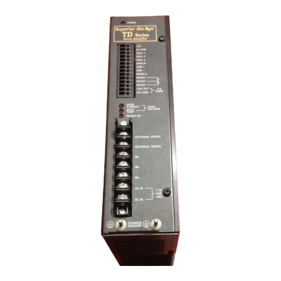
2.4 LED Specifications POWER OVER CURRENT OVER TEMPERATURE REGEN ON Figure 2.2 LED’s Power LED: The power LED indicates that there is AC power applied to the drive and that the logic supply is active. Over Current LED: The over current LED, when active, indicates the possibility of a short circuit from phase to ground or phase to phase. -
Page 10: Current Specifications
2.5 Current Settings: The current settings of the drive reflect the continuous current capability of the motor. Peak current is twice the continuous current setting. The TD-04 has a maximum continuous current of 4 amps and a peak current of 8 amps. The TD-08 has a maximum continuous current of 8 amps with 16 amps peak current. The highest DIP switch setting in the on position will be the max. -
Page 11: Installation
3.0 INSTALLATION 3.1 Mounting The servo drive is intended to be mounted with the brackets supplied with the unit. When selecting a mounting location, it is important to leave at least 2 inches unrestricted space around the top, bottom, and sides of the unit to allow for proper airflow for cooling. -
Page 12: General Wiring Guidelines
3.2 General Wiring Guidelines Dangerous voltages, currents, temperatures, and energy levels exist within this unit, on certain accessible terminals, and at the servo motor. NEVER operate the unit with its protective cover removed! Caution should be exercised when installing and applying this product. Only qualified personnel should attempt to install and/or operate this product. - Page 13 In some extreme cases of interference, it may be necessary to add external filtering to the ac line(s) feeding the affected equipment, or to use isolation transformers to supply their ac power. NOTE: Superior Electric makes a wide range of ac power line conditioners that can help solve electrical interference problems. Contact 1-800-SUP-ELEC (1-800-787-3532) for further assistance.
-
Page 14: Ac Power Wiring
3.3 AC Power Wiring The ac input power, , is connected to the 7 position terminal strip at the connection points marked AC IN and the chassis ground. The terminals are labeled as follows: Neutral Line to Line Connected Connected Terminal System System... -
Page 15: Motor Wiring
3.4 Motor Wiring The motor wiring is connected to the 7 position terminal strip at the connection points marked Ma, Mb, and . Refer to figure 3.2. The motor ground is connected to the Chassis Ground provided. The terminals are marked as follows: Terminal Connection Motor Phase A... -
Page 16: Regenerative Resistor Connections
3.5 Regenerative Resistor Connections An external regenerative resistor can be connected to the 7 position terminal strip connection points marked external regen, . Refer to Figure 3.2. See the following example to determine if an external regenerative resistor is required. For determining if the internal regenerative resistor is sufficient use the following formula: = Inertia of the rotor in lb-in-sec rotor... -
Page 17: Control Wiring
3.6 Control Wiring The control wiring is grouped together on the terminal strip based on their origin. The hall sensor power and signals get connected to the motor. The command signals, the enable, and the ready signal typically connect to the controller. (see Figure 2.1). The 24 volt supply is for customer use and is not ground referenced. The use of shielded cable is recommended. -
Page 18: Operation
4.0 OPERATION 4.1 Introduction The TD330 series operates as a torque mode amplifier. When the drive is enabled and there are no internal shutdowns, a voltage present between the CMD inputs gets translated into motor current. This current creates torque in the motor which yields a rotational force. When connected to a motion controller such as the MX2000, the commanded voltage is issued from the MX2000. -
Page 19: Protective Features
4.4 Protective Features 4.4.1 AC Line Fusing The AC line is protected by fuses located inside the unit on the circuit card near the input terminals. Since access to the fuses requires disassembly of the unit and an open fuse would normally indicate a drive malfunction, such as a blown output IGBT, it is recommended that the unit be returned to the factory for repair. -
Page 20: Troubleshooting Guide
5.0 Troubleshooting Guide Dangerous high voltages exist in the TD330 drive products. Be certain the power has been removed for 5 minutes before any service work is performed. Caution Symptom: Power LED does not come on Verify that the AC power to the unit is between 95 and 264 Vac. Ensure there are no short circuits or heavy electrical loads on the +5 Vdc or +24 Vdc supplies. - Page 21 External regenerative resistors are a shock and temperature hazard. Regen resistors should be mounted and enclosed properly with safe clearances around the regen resistor enclosures. Proper ventilation must also be provided for cooling purposes. Caution Symptom: Motor operates erratically Verify the motor is compatible with the drive. Verify the current setting is for the motor being utilized.
-
Page 22: Appendix Ace Compliance Installation Requirements And Information
Appendix A CE Compliance Installation Requirements and Information Certain practices must be followed when installing a TD servo drive or a TDC servo drive/controller in order to meet the CE Electromagnetic Compatibility (EMC) Directive (89/336/EEC) and the Low Voltage Directive (73/23/EEC). The TD family of products are components intended for installation within other electrical systems or machines. - Page 23 Appendix A - CE Compliance Artisan Technology Group - Quality Instrumentation ... Guaranteed | (888) 88-SOURCE | www.artisantg.com...
-
Page 24: Warranty Information
!"##"$%&'"$(')*+*%"%*,$',-')*".*)*%& !"#$%&'%( )*$+,%&+( -,.$( /0'1#234/56( 7%&8,'*6( 0'33$+,&+",6( 92%%23,8( ,'( ,.$( :&%8,( $3;( "8$%( #"%+.28$%( -,.$( /#"%+.28$%/5( ':( $<"$3, 123":2+,"%$;(=4(,.$(0'1#234(,.2,(8"+.($<"$3,6(&:(3$96("3"8$;(23;(&3('%&>&32*("3'#$3$;(+2%,'38(2,(,.$(,&1$(':(#"%+.28$6(9&**(=$(:%$$ :%'1( ;$:$+,8( &3( 12,$%&2*( 23;( 9'%?1238.&#( "3;$%( 3'%12*( "8$( 23;( 8$%@&+$( :'%( 2( #$%&';( ':( '3$( 4$2%( :%'1( ;2,$( ':( 8.$3,( :%'1( ,.$ 0'1#234A8(:2+,'%4('%(2(92%$.'"8$(':(,.$(0'1#234(&3(,.$($@$3,(,.2,(,.$($<"$3,(&8(#"%+.28$;(:%'1(,.$(0'1#234('%(:'%(2(#$%&';(': '3$(4$2%(:%'1(,.$(;2,$(':(8.$3,(:%'1(,.$(="8&3$88($8,2=*&8.1$3,(':(23(2",.'%&B$;(;&8,%&=",'%(':(,.$(0'1#234(&3(,.$($@$3,(,.2,(,.$ $<"$3,(&8(#"%+.28$;(:%'1(23(2",.'%&B$;(;&8,%&=",'%C... - Page 25 (?@AB?CDA?EF'1EG@AH%EH1EG@A'GFI'*FAJBFGA?EFGK !"#$%&'%(!VWM!XQ(#%';"+,8(2%$(2@2&*2=*$(9'%*;9&;$(,.%'">.(23($Y,$38&@$(2",.'%&B$; ;&8,%&=",'%(3$,9'%?C((D.$8$(;&8,%&=",'%8('::$%(*&,$%2,"%$6(,$+.3&+2*(288&8,23+$ 23;(2(9&;$(%23>$(':(1';$*8('::(,.$(8.$*:(:'%(:28,$8,(#'88&=*$(;$*&@$%4(23;(8$%@&+$C Z3(2;;&,&'36(!"#$%&'%()*$+,%&+(82*$8($3>&3$$%8(2%$(+'3@$3&$3,*4(*'+2,$;(,'(#%'@&;$(#%'1#, 2,,$3,&'3(,'(+"8,'1$%8A(3$$;8C((02**(,.$(3$2%$8,('::&+$(*&8,$;(:'%('%;$%&3>(23;(2##*&+2,&'3 &3:'%12,&'3('%(:'%(,.$(2;;%$88(':(,.$(+*'8$8,(2",.'%&B$;(;&8,%&=",'%C *F'6=4="='GFI'1GFGIG LNL([&;;*$(!,%$$, 7%&8,'*6(0D(KSK\K D$*](NSKM^N^MJ^KK _2Y]((NSKM^N`MO\LS 0"8,'1$%(!$%@&+$]((\MNKKMaNaML^LO T%';"+,(H##*&+2,&'3](\MNKKMaNaML^LO T%';"+,(V&,$%2,"%$(P$<"$8,](\MNKKMaNaML^LO _2Y](\MNKKMaSSMSLSS *F'0DBELJ G2%3$%()*$+,%&+(-Z3,C5(Z3+C V2(T&$%%$&%$ 0bM\KO`(c&**2%8M!,$M0%'&Y6(!9&,B$%*23; D$*](J\(O\(SL\(LL(^^ _2Y]((J\(O\(SLS(Ka(KJ 999C8"#$%&'%$*$+,%&+C+'1 383 Middle Street • Bristol, CT 06010 (860)585-4500 • Fax:(860)589-2136 JKKKLKMNO(P$@C(I )0Q(RNJSOS T%&3,$;(&3(UC!CHC Artisan Technology Group - Quality Instrumentation ... Guaranteed | (888) 88-SOURCE | www.artisantg.com...
Need help?
Do you have a question about the SLO-SYN TD Series and is the answer not in the manual?
Questions and answers