Table of Contents
Advertisement
Quick Links
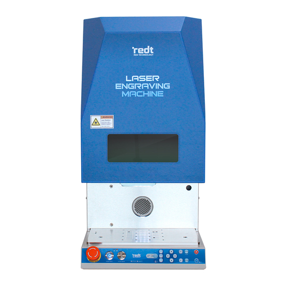
Laser Marking Machine
L100
User manual
◆ Make sure to read the User Manual before using this machine.
◆ This product's appearance and specifications are subject to change without notice for
performance improvement and ease of use some parts may be different the pictures
shown in this Manual.
V.1.0
www.redt.co.kr
3F, (1314 Gwanpyeong-dong) 13-10, Techno 2-ro, Yuseong-gu,
Daejeon, Republic of Korea, 340-12
TEL: +82-70-7011-0905 FAX: +82-42-673-0905
Copyright ⓒ RED Technology since 2005
Advertisement
Table of Contents

Summary of Contents for REDT L100
- Page 1 Laser Marking Machine L100 User manual ◆ Make sure to read the User Manual before using this machine. ◆ This product’s appearance and specifications are subject to change without notice for performance improvement and ease of use some parts may be different the pictures shown in this Manual.
-
Page 2: Table Of Contents
Contents Cautions for Use ............................2 Cautions on Laser Products ........................3 Product parts and installation ......................5 1. Parts and Accessories .........................5 2. Specifications............................7 3. Descriptions.............................8 (1) Product ..............................8 (2) Buttons ..............................9 4. Installation ............................. 10 (1) Installation of Marking Machine ................... 10 (2) Driver Installation ........................ -
Page 3: Cautions For Use
Cautions for Use Please be sure to read and follow the instructions below for safety use. Intended use: L100 is intended for laser marking The instructions below are intended to prevent personal injury and property damages. Please read carefully and use the machine properly. -
Page 4: Cautions On Laser Products
Cautions on Laser Products CAUTIONS The front part of the head has a shield (L100: The control and operation of the laser 1,064nm or higher wavelength, 6 or higher generator (CLASS 4) in a way other than its optical density). Do NEVER expose yourself... - Page 5 * For safe operations (Laser Class 1 Safety), Stay alert all the time when using the laser system.* Laser generator specifications This product uses laser generator. In accordance with IEC60825-1, JIS C6802 and FDA(CDRH) Part 1040.10, CLASS 4 was adopted. - CLASS 4: Approach to laser is very dangerous to the eyes and skin.
-
Page 6: Product Parts And Installation
Product parts and installation 1. Parts and Accessories The L100 provides the following accessories besides the base unit. Their composition may differ depending on options. Name Picture Quantity Usage Power supply ※ Use the power cable connected to the Power Cable grounded outlet. - Page 7 For holding a variety of shape of Medal Clamp materials in place. Medal Clamp For holding of irregular shaped material. For holding a variety of shape of L type clamp materials in place. Dust & smoke discharge Blower *There may be parts not homologous with the manual.
-
Page 8: Specifications
2. Specifications Laser safery classification Class 1 Power consumption AC 100~120V/ AC 200~240V Frequency 50/60Hz Operating voltage < 400W Blower power port 110~220V/2A Dimensions 358*550*585 (W*H*D) Weight 45Kg Max.engraving area Flat: 112(X)*112(Y)*115(Z)mm / Rotary: 85(A)mm Minimum line width 0.05mm Marking speed 3000mm/sec(X,Y) / 18mm/s(Z) Temperature 15 –... -
Page 9: Descriptions
Do not stare at the specular/diffuse reflection of laser. It may result in blindness. Protects the eyes from laser radiation during laser marking. Laser-shielding Display ※L100: Wavelength to protect: 1064nm/ Optical density: OD6 Connects the power cable of the rotary clamp with the Circular Connector product and controls the A-axis of clamp at the use of rotary clamp. -
Page 10: Buttons
(2) Buttons * All buttons but POWER and EMERGENCY SWITCH are inactive until the program is connected. Connect the program and start the system. EMERGENCY SWITCH Emergency stop POWER Product power button VACUUM Vacuum dust collector power button MODE Mode switch ·... -
Page 11: Installation
4. Installation ※ Please follow the instruction below in order for use the solution. ※ This program requires windows OS 7 or later. (1) Installation of Marking Machine L-100 is a desktop CNC marking system. Marking can’t be done with the product only. It should be connected to the personal computer, and the program provided should be used together for marking. -
Page 12: Driver Installation
(2) Driver Installation 1. Go to [Device Manager], And select the [USBLMCV2] using by the mouse right buttom. Then select the [Update driver]. [Mouse right button click] 2. Follow the instructions below. ① Select [Browse my computer for driver software]. ②... -
Page 13: Program Installation
5. Click “Close” button to complete program installation. (3) Program Installation Once the CD provided is inserted into the CD drive, the installation program is automatically being executed. Unless the program is automatically run even after the CD is inserted, start the program in “Computer – CD Drive”. - Page 14 - Program Description Once the installation is completed, the following icon appears on the desktop. The description on the icon is as follows: As a design & marking software program, it features the following functions: marking design, marking option, Toolpath setting, transfer of Toolpath data. As a product setting program, It features the following functions: Laser focus, Guide laser, Roatary origin, Manual calibration.
-
Page 15: Manual Calibration
(4) Manual Calibration Check the setting value on the product’s left side. ✽It has different setting value each machine. Manual Calibration 1. Model: G-F-J30R-J112F163-1-2 2. Focus Length: 1885 3. Guide Laser X: 5000 4. Guide Laser Y: 5002 5. Guide Laser Width: 1015 6. - Page 16 2. Click the [Edit] button. 4. Enter the setting value, then click the [Apply] button.
- Page 17 5. Click the [Yes] button, then the program will start. 6. Run the [machest]. And select the [Manual Calibaration] then select the [Correction] 7. Click the [Yes] button, then the program will start.
-
Page 18: Installation Of The Blower
(5) Installation of the blower ※Blower set is purchased separately. -Order to connect the blower Out take In take Machine Outlet Connect the hose to the outlet. After connect the hose clamp, Then screw the bolt by the wrench. -
Page 19: Auxiliary Power Device Setup (For External Devices)
(6) Auxiliary Power Device Setup (for external devices) ※ It is an option accessory. Auxiliary Power Device is required when using the Dust Collector. This device must be used if the external blowers or dust collectors have more than 2 Ampere. Otherwise, this may result in a machinal failure. -
Page 20: Operation Of Marking Machine
1) Switch on the marking machine. 2) Start the program and connect it to the machine. Once connected, the system is reset, and the cover is automatically opened. 3) Put the material on the working area. (ex: Metal medal for Fiber Laser machine L100) - Page 21 4) Prepare the design to mark. 5) Click the [Marking machine] button and send the marking data.
- Page 22 6) Set the laser focus, using the buttons. (ex: Metal medal for Fiber Laser machine L100) * Height is adjustable on the program [laser option-Laser Focus-Material Height]. 7) Click [Engrave] and send data. Then, check the marking position. 8) Click [Start] or press [...
-
Page 23: Other Devices
6. Other Devices [External Device] - Blower power prot : 110~220V/2A 1. Connect the power to the back of machine. 2. Click [OTHERS] in the [Setup Machine]. 3. In case the AUTO checkbox is clicked in the External Device, the external device is automatically operated even though the power is switched off. - Page 24 [Foot Switch] 1. Connect the power cable to the back of L100. 2. Click [OTHERS] in the Engraver Settings. 3. Able to use Foot Switch for user convenience such as repetitive operation KEY Mapping -Start: The system starts if the Foot Switch is pressed.
-
Page 25: Clamp
7. Clamp A guideline can be checked at the working area. The working area of product is L100 = 112x112(mm). Put the material on the middle of the working area. The guideline of the working area is same with the working area of MagicArt. - Page 26 < Medal Clamp> ※Medal clamp is purchased separately. Clamp Fixing part Pin holes Fixing knob Fixing knob The holding part of clamp is step type, so set the clamp to the step to match the size and thickness are matched. If you move the clamp moving bar to the upside, then turn the fixing knob to the right, the clamp will be tightened.
- Page 27 2. Connect the clamp pins to the clamp fixing unit. 3. Fix the pin on the clamp. Pin holes on the clamp ensures easier holding of irregular shaped material. 4. Fix it by turning the fixing knob.
- Page 28 <L Type Clamp> ※L type clamp is purchased separately. Knob Put the material tightly on the fixing bracket. - Origin Setting Set the L type clamp position to locate the focus at the center of the L type clamp groove. The end position is the origin of L type clamp.
- Page 29 2. Put it tightly on working area with the clamp as a guide. Then, fix the position of L type clamp. 3. Set the focus, using the buttons. 4. Adjust the position of L type clamp to locate the origin of the focus in the middle of the L type clamp groove.
- Page 30 -Material Focus Setting 1. Put the material on the fixing bracket. 2. Set the focus, using the buttons.
- Page 31 <Honeycomb Table> ※Honeycomb table is purchased separately. 1. Put the honeycomb table on the honeycomb table tray. 2. Set the position of honeycomb table on the machine.
- Page 32 <Rotary Clamp> ※Rotary clamp is purchased separately. Connect the clamp fixing part to the working area hole. Connect the cable with the product and switch on the power. Angle Adjustment Handle Power Button Clamp Fixing Part Marking Machine Cable Rotary Clamp Graduations Angle Fixing Knob The rotary clamp graduations are used in...
- Page 33 3. Connect the clamp pins to the rotary clamp fixing unit. 4. Connect the product cable in the rotary clamp to the machine body. *Please match to the groove. There is a risk of breakage if connected without alignment. 5. Switch on the rotary clamp. 6.
- Page 34 - Holding method for outer diameter engraving Put the ring into the chuck finger and fix it with the chuck handle. Holding method for inner diameter engraving Insert the ring by widening the chuck finger of rotary clamp. Then, fix it with the chuck handle. - Holding method for thin ring inner diameter engraving When marking the thin rings, change to the 2mm chuckfinger by using the chuck finger spanner provided along with the product to release.
-
Page 35: Program Usage Description
Program Usage Description Run the program, then a window will show up as below. The program window is different in accordance with modes. The names of parts for each case are as follows. ◈ Program screen Toolbar Menu Template category Template list Work area... - Page 36 ◈ Object selection mode After entering text, click [Selection] button with a mouse or right-click the work area. Then, the entered text object is selected and it turns into selection mode. Double click the selection mode to convert it into text input mode. Object property Object selection mode ◈...
-
Page 37: Toolbar
1. Toolbar ◈ Alignment tools [Line/Curve] Click a certain point and drag it to make a dot line appear. Designate the distance and click with the mouse and then right-click to create a straight line. At this time, press “Ctrl” key on the keyboard and move the mouse to create a horizontal line or a vertical line. - Page 38 Click button on the circle object property window to transform into a pie (a filled arc). The starting/ending degree can be designated and those degrees can be adjusted by dragging the starting/ending degree of the pie with the mouse. At this time, click button to create a reversed image.
- Page 39 [90˚CW] Rotate the selected object by 90˚. [Vertical center in page] [Horizontal center in page] [Center in page]...
- Page 40 Align to the left of base object Align to the center of base object Align to the right of base object Alignment Align to the top of base object Align to the center of base object Align to the bottom of base object Adjust horizontal gap Expand horizontal gap Adjust vertical gap...
- Page 41 ◈ Object tools [Design sample] Import design sample or save current object as design sample. What is a design sample? It means design objects saved in the design sample library. The design sample is easily and quickly imported from the design sample library and freely edited.
- Page 42 [Selection] It is available either to select the object created in the work area to adjust its size and location or to change the object’s property. Only the selected objects are subject to change their options such as location, size, etc. In the text input mode, convert to selection mode easily by right-clicking the work area. [Object selected] [No object selected] [Text input]...
- Page 43 [Drawing pen] Subject can be drawn by dragging the mouse. The thickness of drawing line can be adjusted in the drawing object property window. [Outline stroke of object] The image in a rounding box can be inserted into the target page...
- Page 44 [Invert color of overlapped area] When two or more objects are overlapped, the color in overlapped area can be inverted. Move the target object over the first object after clicking button, then overlapped area’s color will be converted.
- Page 45 When converting text, drag the target object over the text after clicking button. • [Invert color in overlapped area] function is only applied to straight lines, curved lines, circle, rectangle, polygon, design sample and uploaded SVG file, not texts and images. •...
- Page 46 [Line eraser] Clear the line of object. Move the mouse over the line of object, then click the line. The line will be erased (Some objects cannot be erased with the Line eraser tool). ◈ Toolpath Toolpath? Toolpath is a pathway where tool goes by for marking. Toolpath is usually displayed in red color and marking tool goes on the pathway as it engraves.
- Page 47 ◈ Origin point tools [Left top origin point]...
- Page 48 [Left bottom origin point] [Center origin point]...
- Page 49 ◈ Basic tools [New document] Open a new file.
- Page 50 [Open] Open a file in “*.dgn” file format. Select a file on the “Open” window and click “Open” button. [Save document] Save the design drawn on program by “*.dgn”. Choose the location(folder) in which the file will be saved and enter the file name before clicking “Save” button.
- Page 51 [Paste] Paste the cut or copied object. If Ctrl+V is pressed on the keyboard, the same function will be executed. [Undo] Return the work recently done to its previous state. The number of undo stage can be adjusted with Tool menu → Option → General. Undo Change font [Redo]...
- Page 52 ◈ Screen zoom in/out/move tools [Zoom in] The screen is zoomed in by one level. [Zoom out] The screen is zoomed out by one level.
- Page 53 [Zoom in/out ratio] If any screen ratio is selected, the screen in the size of the selected ratio will be seen. [Magnifier] Drag a certain spot with the mouse to enlarge it. [Fit to object] Enlarge the selected object to make it filled in the screen. [Fit to page] Adjust the page size to see the whole work area.
-
Page 54: Text Object Property
[Panning] Drag the screen with the mouse to move it. 2. Text object property If any text object is selected, the property of the text object will appear on the left of the screen. [Font] Designate font. Either click the font’s arrow or click “Preview” button to designate font. - Page 55 Right click to display menu on font preview window. Click “Show Font List”, then you can designate the fonts that will be used in preview. [Mouse right button click] [Size] Adjust the size of the selected text. Either press the size arrow button to select or press [size] button to adjust the size by one level.
- Page 56 [Italic] Change the text style to italic. [Reduce or increase font weight by one level] Adjust the weight of font. [Symbol] Insert symbols. [Text change] The entered text of the selected object can be displayed and changed. Edit the text on the text field or press button to change the text more easily when several text objects are selected.
- Page 57 [Align] Align characters to the left in the text box. [Align to left] Align characters to the horizontal center in the text box. [Align to center] Align characters to the right in the text box. [Align to right] Align characters to the both direction evenly in the text box. [Both] Align characters to the top in the text box.
- Page 58 Arrange characters horizontally. [Horizontal text ] Arrange characters vertically. [Vertical text] Move the selected character horizontally (left, right). Move the selected character vertically (up, down). Adjust the width of the selected character. Rotate the selected character.
- Page 59 [Position/Size] Location of the selected object Size of the selected object When “Keep Ratio” is checked, width and height of the selected object is maintained at the same rate. When “Keep Ratio” is un-checked, width and height of the selected object is adjusted separately.
-
Page 60: Rotation Tool Property
3. Rotation tool property [Rotation] Rotate the selected object by designated degree. Enter the desired angle of rotation, and then press arrow button. object is rotated by the angle entered. Rotate the selected object at the same degree as entered. Rotate and add a new object at the same degree as entered... -
Page 61: How To Engrave For Each Toolpath
4. How to engrave for each toolpath Toolpath? Toolpath is a pathway where tool goes by for marking. Toolpath is usually displayed in red color and marking tool moves on the pathway as it engraves. [Cut-out toolpath] Creates a toolpath that will cut out the selected object. The toolpath boundary will be wider than the selected object’s boundary depending on the diameter of tool [Outline toolpath] Creates a toolpath that will engrave the selected object’s border. - Page 62 [Scan line toolpath] Creates toolpath that will engrave inside area of the target object’s boundary. “Scan line toolpath” might be similar to “Hatching toolpath”, but it is rather used for logos, patterns or objects with larger area. [Single line toolpath] Creates a toolpath that will engrave the center line of the selected object.
- Page 63 [Simulate toolpath cut] The prospected image of the toolpath outcome processed by the selected tool is shown. The following is an example of the cutting toolpath that uses 0.6mm endmill cutter. [Show toolpath only] Only toolpath is shown on the screen with temperately masking all of other objects. If this button is pressed once again, all objects will be seen again.
-
Page 64: Create Toolpath
5. Create Toolpath Select the laser beam. Each engraving option value can be changed by Laser Beam Info pressing Edit or Add button. Hatching gap, depth, engraving speed and others are pre-set for each engraving option. Therefore, it is not necessary to designate hatching Preset gap, depth, engraving speed and others every time and they will be automatically set with their pre-set values. - Page 65 A Toolpath is created in the left diagonal direction A Toolpath is created in the right diagonal direction A Toolpath is created in the cross hatched direction ※ This toolpath is not recommended due to possible damage to materials with plated surface. If this option is un-checked, a toolpath for only the inside of the selected object is created.
- Page 66 (2) Preset: Add/Delete/Edit If “Edit” button is checked, Add/Delete/Edit buttons will appear. Enter a name to the preset option setting window and designate hatching gap, engraving depth and etc before clicking “OK” button. The option will be added to the preset option selection list. Select an option to be deleted and click “Delete”...
-
Page 67: Nc Data Output
6. NC data output Select toolpath and click product button on the top-right of screen to transfer the selected toolpath to the product. When the machine is identified, the model name will appear on the button. “NC output” window appears when this button is clicked. On the NC output window, select a measuring method and other options, then click “Start Engraving”... - Page 68 [Transfer of Tool Path Data Right after Text Entry] Able to mark a selected object immediately without creating a tool path Able to select a marking method such as edge and scan line Type of A tool path is automatically generated by the selected marking method. Options Engraving can vary depending on a type of the selected tool path.
- Page 69 Hatching interval and direction are already set by option. Therefore, if a tool path Preset option is chosen, the preset values are automatically set. Displays a tool path according to the selected fragment option Toolpath Preview ex> Select the scan line Able to mark a selected object repeatedly with a certain width/length interval It allows users to automatically fragment a lot of works at a time by entering clamp Multiple...
-
Page 70: Laser Option
Laser Option Click the [ (IMP-L100)] button / [Toolpath] button to send the Toolpath. Then, a laser option window pops up. Adjust the laser option and click [Engrave]. Then, the marking data are sent to the product. Engraving object Checks the object to engrave... -
Page 71: Engraving Option
1. Engraving Option Laser options such as engraving type, power and speed can be set in advance. Press [EDIT] and click the button at the bottom. Then, you can change options. <Add> This menu is used to add a new engraving option. Set the options (e.g., name, engrave type, power, frequency, speed, etc.) and click [Save]. - Page 72 <Edit> This menu is used to edit engraving options. Edit the options and click [Save]. <Delete> Deletes engraving options...
-
Page 73: Options
2. Options Engraving types can be selected. Laser options change depending on an engraving type. Adjust the value and click [Save Option]. 3. Material The height of laser focus can be set by material. Press [Edit] and click the button at the bottom to change options. <Add>... - Page 74 <Edit> This menu is to edit material setting. Change the option and click [Save]. <Delete> Deletes the material option...
-
Page 75: Rotary Engraving Option
4. Rotary Engraving Option In case of rotary engraving, the diameter and width information which were entered at design by MagicArt is reflected and stated as it is. Then, laser focus is automatically set, using the value. In case of inner diameter, angle is calculated and informed. -
Page 76: Laser Option By Toolpath
5. Laser Option by Toolpath There are differences in laser options by Toolpath. <Cutting Toolpath> - Overpath: Improves cutting completeness by cutting from the starting point to the preset value with laser. - Move Focus: Same with the focus depth setting. When cutting the engraving depth little by little, designate the depth. -
Page 77: Markingprocess
Thickness 2. Place the material on the working area and set the laser focus, using buttons. (Ex: Fiber laser machine L100/ aluiminum pandant) 3. Once a template appears, click [ (Enter/edit characters)]. Move the mouse pointer to a wanted position and click it. Then, enter the characters. - Page 78 (alignment in the middle of a work area)]. 5. Once the design is completed, click [ (Scanned line Toolpath)]. A Toolpath refers to a path way of tools. ✽ Click [ (IMP-L100)] on the right top without creating a Toolpath for immediate Marking.
- Page 79 6. Select an option on the Toolpath page. If necessary, set the hatching interval and click [Create Toolpath]. 7. A Toolpath object is being created. Click [ (IMP-L100)] on the right top.
- Page 80 8. If the NC Output window appears, click [Start Engraving]. 9. A laser option window pops up. Select the Laser Option and click [Engrave]. Then, a Start page appears with a warning message. Click [Start]. (If the laser focus is set in advance when a material is placed, it is unnecessary to enter height at a laser option.)
- Page 81 10. Once a red laser pointer on the material is turned on, check and adjust the position of the pointer, using the direction keys. The area pointed by the red rectangular laser pointer refers to an actual marking zone. The round laser pointer in the middle represents the origin of the height of laser focus.
-
Page 82: Marking Process Of Ring Inner/Outer Diameter
Marking Process of Ring inner/outer Diameter ● Machine: Fiber Laser Machine L100 ● Clamp: L type clamp or Rotary clamp (Optional) ● Material: Metal ring ● Toolpath: Scanned Line ◈ Preparation 1. Measure the width and diameter of a ring to be engraved. - Page 83 2. When “Insert Rotary Object Template” window appears, enter the measured width and diameter of the ring and click “OK.” 3. The template appears at the center of the screen. 4. Select [Text Input] on the toolbar, and click the work area using mouse and enter text to be engraved.
- Page 84 5. After entering text, press [Selection] on the toolbar to enter the object selection mode. Select the text, and edit the size and font of the object. To place the object at the center of the work area, click [Center in Page] button. Handle to adjust character gap Handle adjusting gaps between characters?
- Page 85 7. Once “Hatching Toolpath” window appears as shown in the picture below, select tool, toolpath gap and depth, and click “Create Toolpath” button. -Marking at Fixed Angle when rotary marking: Engrave the each text. 8. The “Toolpath” object is created as below and usually marked with red line on the screen. Scroll the mouse wheel to enlarge the toolpath object, and if it is not the desired toolpath, delete the toolpath and create it again by adjusting the toolpath option.
- Page 86 9. The toolpath angle is shown as below based on the entered ring size data and text length. 10. After selecting one or more created toolpaths, click button. 11. Once “NC Output” window appears, click “Start Engraving” button.
- Page 87 <When marking the outer diameter> - L type clamp ※L type clamp is purchased separately. -Roatary Clmap ※Rotary clamp is purchased seaperatly. When operating with rotary clamp, a marking error can be reduced by measuring the height of a material and entering it into a program.
- Page 88 <When marking the inner diameter> If inner diameter is selected, it is able to check angles automatically stated, using the diameter and width values. *In case of inner diameter marking outside the limit of 20°, marking may not be possible. *If outside the indicated angle and the marking position, marking may not be possible.
- Page 89 After loosen the angle fixing knob, Adjust the angle by turning the angle adjustment handle. *Adjust the angle based on the bottom of the angle bar. Then fix it by turning the angle fixing knob again. When operating with rotary clamp, a marking error can be reduced by measuring the height of a material and entering it into a program.
- Page 90 For ring inner diameter marking, measure the height after specifying a marking surface according to the marking position. E.g.1) In case the outside of the inner diameter of a ring is marked, measure and enter the height of the outside of the secured ring. Then, measure the height based on the center point of the marking area.
- Page 91 12. A laser option window pops up. Select the Laser Option and click [Engrave]. Then, a Start page appears with a warning message. Click [Start]. (If the laser focus is set in advance when a material is placed, it is unnecessary to enter height at a laser option.) 13.
- Page 92 14. Once the marking position setting is done, click the program Start button or [ ] on the product ong (2 seconds or longer). Then, the cover is automatically closed, and marking begins.
-
Page 93: Photo Marking
Photo Marking What is photo marking? This is an marking method to display the shade of image with dots. ● Machine: Fiber Laser Machine L100 ● Material: Metal pendant ● Toolpath: Photo Impact Engraving 1. Place the material on the working area and set the laser focus, using buttons. - Page 94 3. Adjust the size and location of the image. [Mouse drag]...
- Page 95 4. [Clipping Mask] function enables cutting out target area extracted from the image. Create a shape to designate the target area and drag it on to the image. [Mouse drag] 5. Drag a mouse to select the target area and the whole image. [Mouse drag]...
- Page 96 6. Select [Transform] menu → [Make Clipping Mask]. 7. The target image remains except the outer image. The whole actual image is already saved in the file, not erased.
- Page 97 8. Click [Photo Impact Engraving Toolpath] button. 9. Adjust marking option in photo marking option window. ✽ The black area cut by clipping mask is not being engraved. When marking a photo, bright part (white area) of image is expressed in dots. Since darker image shows higher quality, adjust the brightness darker.
- Page 98 10. Click “OK” button to create toolpath for photo marking. Double check the created toolpath and click button. When marking a photo, white area of image appears as a dot. So the result of the toolpath is shown as negative image. 11.
- Page 99 12. A laser option window pops up. Select the Laser Option and click [Engrave]. Then, a Start page appears with a warning message. Click [Start]. (If the laser focus is set in advance when a material is placed, it is unnecessary to enter height at a laser option.) 13.
- Page 100 14. Once the marking position setting is done, click the program Start button or [ ] on the product long (2 seconds or longer). Then, the cover is automatically closed, and marking begins.
-
Page 101: Cutting Process
Cutting Process ※Honeycomb table is purchased seaperatly. 1. Measure the thickness of a material to be cut. 2. Place a material to be cut on the honeycomb table and place it on the working area. Then set the laser focus, using buttons. - Page 102 4. After entering text, press [Selection] on the toolbar to select the text and designate the font. Adjust the text to the desired size. The size can be adjusted by using an object handle(a square in the picture below) as below, or from the object property window. Object Handle 5.
- Page 103 If the gap of some characters is partially adjusted, press [Text Input] button and drag the mouse to select characters you want. Drag a text gap adjustment handle with the mouse and adjust the gap. [Enter text] [Press button and click with the mouse] [Select characters] [Adjust character gap] 6.
- Page 104 8. [Copy] and [Paste] the ring type, then guideline for a location of the ring appears. Adjust the location and click the spot. Copy the target object by pressing [Ctrl+C] Paste the target object by pressing [Ctrl+V] Confirm the location and click the spot. 9.
- Page 105 10. Once the design is completed, click [Cut-Out Toolpath]. 11. Once the “Cut-Out” window appears as seen in the figure below, select tool to be used for the cutting, input the measured material thickness and the other options and click “Create Toolpath.”...
- Page 106 12. “Toolpath” is created. 13. Click button.
- Page 107 14. If the NC Output window appears, click [Start Engraving]. 15. A laser option window pops up. Select the Laser Option and click [Engrave]. Then, a Start page appears with a warning message. Click [Start]. (If the laser focus is set in advance when a material is placed, it is unnecessary to enter height at a laser option.)
- Page 108 16. Once a laser on the material is turned on, check and adjust the position of the pointer, using the direction keys. The area pointed by the red rectangular laser pointer refers to an actual marking zone. The round laser pointer in the middle represents the origin of the height of laser focus.
-
Page 109: Curved Material Marking
Curved Material Marking For marking on curved surface, select a curved template. Enter the height and length of the curved surface. Then, z-axis automatically moves along the surface and marks letters one by one. In terms of marking on curved surface, texts are only available. 1. - Page 110 With the curvature information, z-axis shift is calculated. Therefore, if an incorrect size is entered, z-axis error can occur. Height width When entering curvature information, put the material on the floor as shown in the figure. Then, enter the distance between the two points which touch the floor.
- Page 111 3. Send data and start marking. Then, z-axis automatically moves and marks according to angles.
-
Page 112: Shape Distortion
Shape Distortion Due to curvature, text and shape can be distorted during laser marking. If marked under this mode, such distortion can be corrected. - Check the guide laser on your own and enter the distortion value. - This function is available for figures and texts only (NOT for pictures and circular texts). [Figure Shape Distortion] Able to distort the shapes of the figures provided by MAGIC ART Create figures and click [Menu] →... - Page 113 [Text Shape Distortion] If [Distort Shape] is clicked without converting an object into a curve, texts are distorted one by one. 1. Enter texts and click [Menu] → [Transform] → [Convert to Curve]. (Or select an object and right-click → [Convert to Polygon]) * Texts change to figures when converted into curves so that they cannot be edited.
- Page 114 2. Once texts are converted into curves, change [Fill Shape] to [Infill] in the SHAPE on the left.
- Page 115 3. Click [Menu] → [Transform] → [Distortion]. 4. Enter shape and values. If a negative value is entered, a direction of distortion changes. 5. Enter shape and values. If a negative value is entered, a direction of distortion changes.
-
Page 116: Layout Of Text In A Circle
Layout of Text in a Circle Text can be laid out in a circle by using circular text object. [Circular Text] Click button to display “Circular Text” window. Designate direction and angle, enter size and text, then click “OK” button. - Page 117 Adjusting layout angle Drag the first character [R] or last character [y] in the text to adjust the angle of the layout. Drag with mouse to adjust the layout angle. Drag other characters with mouse to adjust the distance to the center of the circle. Drag with mouse to adjust distance from the center of the circle.
-
Page 118: Layout Of Text On A Curve
Layout of Text on a Curve 1. Click the [Line/Curve] button. 2. Click on a certain point with the mouse and designate a distance. Drag the mouse to make a curve appear. Press the right button on the mouse to create the curve. [Mouse drag] 3. -
Page 119: Font Preview
Font Preview Apply the fonts installed on the computer to the text objects and preview the shape to select the most suitable font. Select text object, click “Preview” button in the object property window or right-click the mouse and select “Font Preview”... -
Page 120: Text Change
Text Change The text contents in text objects can be easily changed by the “Text Change” feature. Import a saved design sample, file, or select text objects designed on the screen. Click [Text change] button or right- click the mouse, and select “Text Change” on the menu. Change contents in the “Text Change”... -
Page 121: Template Creation
Template Creation Template is an image corresponding to the materials to be engraved by 1:1 ratio. Load a template that is the most similar to the material to be engraved, and enter the text to be engraved. This way allows you to create the location of marking and the size of text to be engraved more easily and conveniently. - Page 122 3. Select image files (jpeg, bmp, png and etc.) from the “Open” window, and click “Open” button. 4. Input size of the template. Check “Save” to save the loaded image as a template for later use and enter a name for the template. Click “OK”...
- Page 123 ✽ Right-click in the template category window for more template related features. The template can be deleted by “Delete” on the menu that appears by right-click in template list window. [Mouse right button click]...
- Page 124 [Creating template #2] 1. Press [Image] button to import an image. 2. Select Tool menu → Template → Save Selected Object as Template. Type a name of new template on “Input” window.
- Page 125 3. The saved template is added in the template library. The template saved in the “Save Selected Object as Template” menu is saved as designated size to the screen. When loading the template, check “Maintain Original Size”, then the template will be loaded with the original size designated when saving the template.
-
Page 126: Saving As Design Sample
Saving as Design Sample Edited contents can be saved as design sample for easier access to the design. [Saving as design sample #1] 1. Edit contents and select the objects. 2. Click File menu → Save as Design Sample and select a folder or create new folder. Enter the name and click “Save”... - Page 127 [Saving as design sample #2] 1. Select objects, and click [Design Sample] button.
- Page 128 2. Select a folder to save the objects from design sample library window. 3. Click [Save selected image as sample] or right-click the design sample image, and click “Save Selected as Design Sample” menu. Enter the name to be saved, and click “OK” button to save it in the design sample library. [Mouse right button click]...
-
Page 129: Auto Change Of Serial Number
Auto Change of Serial Number Use this function when changing numbers by certain unit. 1. Edit the font and size of text object with number, and press “Alt+N” key on a keyboard, or select Text menu → Serial Number → Advance Serial Number to change the number automatically. 2. - Page 130 3. If the serial number is not regular, then select Text menu → Serial Number → Load Serial Number. Enter serial number in the “Lines to export” field or click “Load File” button to load it from a file (.txt or .csv file format).
- Page 131 Serial numbers can be loaded from comma separated values file (.csv) or text file (.txt). Each row of the file is recognized as one serial number, and the contents of each row separated by comma are shown in the next line.
-
Page 132: Loading And Editing Image
Loading and Editing Image 1. Loading an image This program provides a function to load various types of image files. Supported image file types are as follows. Windows or OS/2’s bitmap graphic file CompuServe graphic file JPG/JPEG JPEG bitmap graphic file Portable Network Graphics bitmap graphic file Z Soft PC paintbrush bitmap file TIF/TIFF... - Page 133 2. When “Open” window appears as the figure below, select the image to be loaded, and click “Open” button. 3. Drag the work area with the mouse to load the image by desired size.
- Page 134 2. Converting and editing image Only single color image can be engraved. Since multiple color images cannot be engraved by product, it should be converted to single color (1 bit) image. [Converting to single color image] 1. Select the image object you want to convert, and click “Convert” button in the image object window and select “Monochrome (1bit).”...
- Page 135 Or select the Transform menu → Bitmap → Mode → Monochrome (1bit). 2. “Color Image to Black & White” window appears as below. Adjust the slider to change it to the most suitable single color, and click “OK” button.
- Page 136 [Editing image] Loaded image can be edited by “Paint” program in Windows. Select the image object to be edited, right-click it to select “Edit” or select Transform menu → Bitmap → Edit. Click [OK] to run Windows Paint program. Then, Windows Paint program will show the image. After editing the image, press “Save”...
-
Page 137: Import A File In Svg Type
Import a File in SVG Type Loading vector graphic files such as SVG file is also supported. The SVG file is created by various graphic programs such as Illustrator, CorelDraw and etc. 1. Select File menu → Save As from Illustrator program to save a file in SVG type. 2. - Page 138 3. Click button to load the SVG file. 4. Or select File menu → Import to import a file.
-
Page 139: Product Setting
Product Setting ※ The product is being released in default setting. Please contact the customer service center before changing the setting. ※ Set the product in the following order: Laser Focus Calibration - Guide Laser Calibration-Rotary Origin Calibration. ※ An product setting program is separately provided. Start the program first to set the marking machine. ※... - Page 140 3. Click [Laser Focus] on the Product Setting. 4. After checking the message, click [Next]. Then, the laser focus calibration procedure appears. Enter the height of a material. 5. Check the warning message and click [Start].
- Page 141 6. The numerals and circles are engraved on the fixed material. The numerals range from ‘01’ to ‘10’. However, the numerals actually engraved can differ depending on the laser focus. 7. Enter the middle number among the engraved numerals on the Engrave Machine Setting page and click [OK].
- Page 142 2. Guide Laser Calibration Calibrates the size and position of a guide laser. 1. Place a material on the working area. ※ Use a metallic material. 2. Click [Guide Laser] on the Product Setting. 3. Check the message and click [Next].
- Page 143 4. Set the size and height of a material (a rectangle to be marked) and click [Apply]. To mark the rectangle, click [Mark]. Then, the cover is automatically closed, and the rectangle is being engraved on the material. Marking Line *A 20mm rectangle is being engraved on the 0.5mm-high material.* 4.
- Page 144 * Select the laser option on the Guide Laser page and adjust laser options.
- Page 145 3. Focus Pointer Set the position of the head laser pointer and V laser pointers. 1. Select [Focus Pointer] in the Engraver Settings. 2. Adjust to make head pointer in the center of the cross on the workspace, using the arrow buttons. Then, click [Next].
- Page 146 3. Place the flat material on the workspace and enter the thickeness. Then click [Next]. 4. Pess the ▶ button on the right and proceed sequentially. (2mm wrench is required.) All step is 4 step, both pointer must proceed in the same way.
- Page 147 4. Rotary Origin 1. Fix the rotary clamp to the working area. 2. Click [Rotary Origin] on the Product Setting. 3. Fix the tool with a sharp edge to the rotary as described below: 4. To position the laser pointer at the tip, adjust the product with the direction keys. Then, click [Next]. Or, adjust the position, using the buttons and click long (1 second or longer).
- Page 148 5. Remove the fixed tool, then Insert the ring into the chuck finger as below, and tighten the rotation clamp to set it. 6. Move to the stage II. And insert the ring size on the program. 7. Move to the [H pointer] to the center of the ring by using arrow buttons. Then, click [Complete].
- Page 149 5. Manual Calibration Reference to the [4. Installation → (4) Manual Calibration] in page 13. 6. Correction When the laser passes the scan head and comes all the way through the lens, the farther it moves away from the central point the greater distortion in shapes and sizes is introduced as shown in the figure on below.
- Page 150 4. Enter the height of the material and click the “Apply” button. Then Click the “Mark” button to start marking 5. Click the “Next” button to move on to the next step. Measure all sides marked with arrows as shown in the figure below.
- Page 151 Make sure that the size is measured from each corner as shown in the figures below. 7. Enter the sizes and click the “Complete” button to finish the calibration process.
Need help?
Do you have a question about the L100 and is the answer not in the manual?
Questions and answers