Table of Contents
Advertisement
STANDARD RADIATOR
IOM MANUAL
H Style
N Style
VB Style
INSTALLATION,
OPERATION AND
MAINTENANCE MANUAL
FOR ALL STANDARD
RADIATOR MODELS
HB Style
F Style
V Style
To access digital copies of this
manual, other manuals or
additional information, scan the
July 2019
code on the left or visit
www.rocore.com
Advertisement
Table of Contents

Summary of Contents for Kelvin ROCORE VB Series
- Page 1 STANDARD RADIATOR IOM MANUAL H Style N Style VB Style INSTALLATION, OPERATION AND MAINTENANCE MANUAL FOR ALL STANDARD RADIATOR MODELS HB Style F Style V Style To access digital copies of this manual, other manuals or additional information, scan the July 2019 code on the left or visit www.rocore.com...
- Page 2 ROCORE NOTICE The purchase, installation and use of this product are subject to a Limited Warranty which excludes all other warranties expressed or implied by law. The complete terms and conditions of the Limited Warranty accompany the product packaging and shipping material. If you cannot find or misplace this limited warranty information, please...
-
Page 3: Table Of Contents
TABLE OF CONTENTS I. STANDARD WARRANTY POLICY II. GENERAL INFORMATION Page A. Radiator Model Number Description ......... B. Receiving and Inspection ............C. Storage .................. D. Moving and Lifting ..............E. Safety and Advisory Messages ..........III. INSTALLATION A. Placement and Mounting ............B. - Page 4 IV. GENERAL MAINTENANCE A. Lubrication ................B. Belt Tension ................C. Bolts and Torque Requirements ..........D. Core Cleaning ................. E. Fans ..................F. Coolants ................. G. Replacement Parts ..............H. Miscellaneous Maintenance ............. V. TROUBLESHOOTING ..............
- Page 5 ROCORE HOLDINGS, INC. STANDARD LIMITED WARRANTY 1. Product Warranty 2. Services and Service Warranty 3. Repair and Replacement Procedures 4. Disclaimer of Warranties; Limitation of Liability 5. Dispute Resolution and Governing Law 6. General 1. Product Warranty Rocore Holdings (“Rocore”) warrants to original purchasing customer (“Customer”) that no product produced and sold by Rocore shall fail under normal use and service due to a defect in material or workmanship for the following warranty periods: Product Type...
- Page 6 2. Services and Service Warranty The Standard Limited Warranty covers both parts and labor necessary to repair a defective product, but does not include labor costs related to the removal of a Rocore cooling product or installation of a repaired or replacement Rocore cooling product.
- Page 7 THE LIMITED WARRANTY IS THE SOLE AND EXCLUSIVE WARRANTY GIVEN BY ROCORE AND, WHERE PERMITTED BY LAW, IS MADE EXPRESSLY IN LIEU OF ALL OTHER WARRANTIES, EXPRESS OR IMPLIED, STATUTORY OR OTHERWISE, INCLUDING BUT NOT LIMITED TO IMPLIED WARRANTIES OF MERCHANTABILITY, FITNESS FOR ANY PARTICULAR PURPOSE, DESIGN, PERFORMANCE, CAPACITY, EFFICIENCY AND IMPLIED WARRANTIES FROM COURSE OF DEALING OR USAGE OF TRADE.
-
Page 8: General Information
II. GENERAL INFORMATION RADIATOR MODEL NUMBER DESCRIPTION Number of Split Passes MB S V 02 - 5/3 - 531/472 - 0.75 C - 2/1P Number of Stacked Mechanically Bonded Passes (OR Single Circuit Passes) Special Motor RPM *** * Model Type Motor HP Model Size Split Core Percentage... -
Page 9: Storage
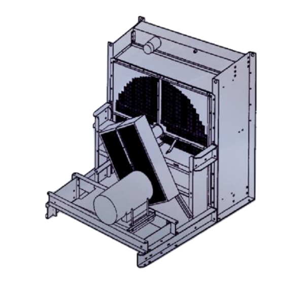
STORAGE All radiators are prime painted and top coated prior to being shipped unless a special finish is specified. When the radiator is not going to be used immediately and is to be stored, it should be kept in a clean, dry place, not subject to rapid change in temperature or humidity and away from heavily traveled areas to avoid the possibility of damage. - Page 10 Step 1 To rotate, move in this direction while lifting CAUTION! See text for more Step 2 detail on lifting and rotating Step 3 NOTE: Refer to the radiator assembly drawing for more exact lifting hole locations. Step 4 Step 5 Hold here to pivot Figure 1A: Rotate from vertical to horizontal NOTE: Refer to the...
-
Page 11: Safety And Advisory Messages
SAFETY AND ADVISORY MESSAGES WARNING! Vertical radiators are WARNING! Over-tensioning belts subject to wind effects and installation shortens belt and bearing life. (See should consider the potentially Section IV. B. for correct belt tensioning) dramatic effect of prevailing winds on cooling system performance. -
Page 12: Installation
III. INSTALLATION PLACEMENT AND MOUNTING The radiator is designed for locations that allow adequate airflow to and from the radiator. For engine mounted radiators, there should be no obstructions in the airstream other than the engine. If ductwork is used on the radiator’s air discharge, its cross- sectional area should be equal to or larger than the core area. -
Page 13: Mounting Surge Tanks On Remote Radiators
3. MODEL ‘F’ TYPE RADIATORS (FAN ON RADIATOR) This type of radiator should be mounted to the engine skid with the mounting holes provided at the bottom of each radiator side member and along the base channels. The customer should provide bracing from near the top of the radiator side member down to the engine skid (See Fig. - Page 14 CUSTOMER SUPPLIED BRACES (2) Figure 2A: Model N engine-mounted radiator installation CUSTOMER SUPPLIED BRACES (2) Figure 2B: Model F engine-mounted radiator installation...
- Page 15 Outlet Figure 3: Mounting surge tanks on horizontal radiators...
-
Page 16: Piping
PIPING The following pages show piping schematics for various applications, one of which should suit your needs. All piping connections to the radiator should be externally supported; not hung on the radiator. Flexible connections are required when connecting piping to a radiator. Piping and connections should be designed to isolate the radiator from vibration and thermal expansion loading. - Page 17 1/4" to 1/2” Vent Line from Thermostat Keep Top Tank 1/4 to 1/3 Housing (If Engine Requires It) Full when Cold Inlet Radiator Outlet Engine Drain Flexible Connections (Typical) Engine Pump NOTE: All lines are shown schematically and all respective circuit piping should be lower than the radiator top tank Figure 4: Engine-mounted radiator piping schematic without deaeration baffle...
- Page 18 Fast Fill Port (If Included) 1/4" to 1/2” Vent Line from Thermostat Keep Top Tank 1/4 to 1/3 Housing Full when Cold Inlet Radiator Outlet Flexible Connections Engine (Typical) Drain Engine Pump 3/4” to 1” Fill Line to Engine Pump Suction NOTE: All lines are shown schematically and all respective circuit piping should be lower than the radiator top tank Figure 5: Engine-mounted radiator piping schematic with deaeration baffle...
- Page 19 Keep Top Tank 1/4 to 1/3 Full when Cold 1/4" to 1/2” Vent Line from Thermostat Housing (If Engine Requires It) Inlet Radiator Outlet Flexible Connections Engine Drain (Typical) Engine Pump Drain Strainer (Optional) NOTE: All lines are shown schematically and all respective circuit piping should be lower than the radiator top tank Figure 6: Vertical remote-mounted radiator piping schematic without surge tank...
- Page 20 Keep Surge Tank 1/4 to 1/3 Full when Cold Surge Tank 3/4” to 1” Fill Line to Engine Pump Suction 1/4” to 1/2” Vent Line 1/4" to 1/2” Vent Line from Thermostat Housing (If Engine Requires It) Inlet Radiator Outlet Engine Drain Engine Pump...
- Page 21 3. HORIZONTAL REMOTE MOUNTED RADIATORS When cooling with a horizontal remote radiator, the system should be piped as shown in Figure 8. A separate surge tank is required and must be the highest point in the system. A 3/4 inch to 1 inch (*) fill line is required from the bottom of the surge tank to the outlet tank of the radiator or the pump suction piping to prevent pump cavitation.
- Page 22 Keep Surge Tank 1/4 to 1/3 Full when Cold Surge Tank 1/4” to 1/2” Vent Line 3/4” to 1” Fill Line to Radiator Outlet Tank 1/4" to 1/2” Vent Line from Thermostat Housing (If Engine Requires It) Inlet Radiator Outlet Engine Flexible Connections (Typical)
- Page 23 1/4” to 1/2” Vent Line Radiator Surge Tank Keep Surge Tanks 1/4 to 1/3 Full when Cold Outlet 3/4” to 1” Fill Line to Radiator Outlet Tank Radiator Inlet 1/4" to 1/2” Vent Line from Thermostat Housing (If Engine Requires It) Strainer (Optional) Engine Surge Tank Auxiliary Pump...
- Page 24 1/4" to 1/2” Vent Line from Thermostat Housing Keep Both Circuits of Top Tank (If Engine Requires It) 1/4 to 1/3 Full when Cold AC Cap JW Cap Engine JW Inlet AC Inlet Radiator JW Outlet Flexible Connections Drain (Typical) Drain AC Outlet Engine JW Pump...
- Page 25 Caps JW Surge AC Surge Tank Split Tank Split 3/4” to 1” 1/4” to 1/2” Vent Lines Fill Lines JW Circuit 1/4” to 1/2” Vent Lines AC Circuit Flexible Connections AC Inlet (Typical) AC Outlet JW Inlet JW Outlet Radiator Engine Engine JW Pump...
-
Page 26: Electrical Wiring
ELECTRICAL WIRING WARNING! THE FOLLOWING SAFETY PRECAUTIONS MUST BE OBSERVED a. Electric rotating machinery and high voltage can cause serious or fatal injury if improperly installed, operated or maintained. Responsible personnel must be familiarized with the installation of electric motors and generators, the National Electric Code, NFPA and all local safety requirements. -
Page 27: Coolant Level Switches
Only use UL listed insulated cables with the following designations: RHH, RHW, RHW-Z, XHH, XHHW, XHHW-Z or XLPE. Do not use designations THHN or any others beginning with ‘T’. When the Total wiring lengths between a VFD and a motor or multiple motors exceeds 100 feet, shaft currents and motor noise can occur. -
Page 28: Coolants
CAUTION! If pressure filling the radiator, note that the maximum operating pressure for most radiators will be 20 psi. See the radiator drawing for the actual maximum operating pressure. Exceeding this pressure may damage the radiator and void the warranty. For radiators with top tank deaeration baffles: the radiator may need to be filled through one of the inlets in addition to filling above the deaeration baffle, unless the radiator is supplied with a special fast-fill port. - Page 29 CAUTION! Do not use over 65% ethylene glycol or over 60% propylene glycol antifreeze by volume. CAUTION! Using a different type of glycol or a different % of glycol mixture than the system was designed for may affect the performance of the system. For example, propylene glycol is more viscous than ethylene glycol and results in more pressure drop and less heat transfer capability.
- Page 30 For best results, the cooling system’s Mixture pH level should be maintained between 8.0 and 10.5. Check your engine manual. Some engines may require slightly different pH ranges. CAUTION! Most Rocore radiators are made of steel, copper, brass and solder materials.
- Page 31 Port “A” Level Switch Radiator In this case, the level switch will indicate a low coolant level when the coolant level falls below Port “A” Figure 12: Radiator coolant level switch installation Surge Level Switch Tank In this case, the level switch will indicate a low coolant level when the coolant level falls below the centerline...
-
Page 32: Fan Drive Components
FAN DRIVE COMPONENTS When your radiator is supplied with a V-belt driven fan, the belt tension will need to be checked frequently by the customer. On remote radiators, belts and sheaves are installed by Rocore. On some engine-mounted radiators, belts and sheaves may be mounted by the customer. - Page 33 Level Fan Sheave Straight Edge Belts Belts Idler Sheave Engine Crank Sheave Figure 14: Sheave alignment...
- Page 34 Radiator Radiator Shroud Shroud Airflow Airflow 2/3 of Projected 1/3 of Projected Fan Width Fan Width Projected Fan Projected Fan Width Width Sucker Fan Application Blower Fan Application Figure 15: Fan position...
-
Page 35: Cogen, Combined Heat And Power (Chp)
COGEN, COMBINED HEAT AND POWER (CHP) & COLD-WEATHER CLIMATE APPLICATIONS Rocore’s limited warranty does not apply to our standard solder-bonded construction radiator products that are used for severe-duty cooling systems such as cogen, heat recovery, combined heat and power (CHP), dump radiators or any other system that subjects the radiator to regular occurrences of thermal shock, unless the system is designed to eliminate the thermal shocking. -
Page 36: General Maintenance
IV. GENERAL MAINTENANCE Within this section are the maintenance duties that must be followed to ensure optimum performance and avoid hazards. LUBRICATION 1. PILLOW BLOCK BEARINGS Some radiators are equipped with bearings that require frequent greasing, depending on the application (See Table 2). Table 2: Greasing frequency guide APPLICATION GREASING FREQUENCY... - Page 37 2. MOTOR BEARINGS Some small motors have sealed-for-life ball bearings, which require no re-lubrication. Regreasable bearings are shipped with a high quality, wide temperature range grease in the bearings. NOTE: Bearings and grease must be kept free of dirt. Bearings should be lubricated while stationary and the motor is warm. Disconnect power to the motor (lockout/tagout).
-
Page 38: Belt Tension
BELT TENSION When your radiator is supplied with a V-belt driven fan, the belt tension will need to be checked frequently. Proper belt tension is necessary for normal belt and bearing life and to provide the required radiator cooling performance. See Section III. -
Page 39: Bolts And Torque Requirements
BOLTS AND TORQUE REQUIREMENTS All bolted joints are properly torqued at the factory and the cooler’s gasketed joints are leak tested. Before initial startup and as a regular preventive maintenance procedure, the radiator should be thoroughly inspected for loose bolts. A typical Rocore radiator may have many different types of bolted joints and torque requirements;... -
Page 40: Core Cleaning
Table 6: Torque to apply for steel bushings BUSHING TYPE BOLT SIZE TORQUE, FT – LBS 1/4 - 20 X 3/4 SH, SDS 1/4 - 20 X 1 3/8 1/4 - 20 X 1 7/8 P1, P2, P3 5/16 – 18 X 1 5/16 –... -
Page 41: Coolants
COOLANTS The coolant should be maintained throughout the life of the cooling system. Testing the coolant is important to ensure that the engine and/or pumps are protected from internal cavitation and that all cooling system components are protected from corrosion, erosion, scaling, boiling and freezing. -
Page 42: Replacement Parts
Table 8: Typical coolant service life Type of Coolant Service Life (1)(2) Conventional supplemental 3,000 hours or one year coolant additives and water Conventional Heavy-Duty Coolant/Antifreeze 3,000 hours or one year ASTM D4985 Conventional Heavy-Duty Coolant/Antifreeze 3,000 hours or two years ASTM D6210 Extended Life Coolant 12,000 hours or 6 years... -
Page 43: Miscellaneous Maintenance
MISCELLANEOUS MAINTENANCE The coolant level should be checked regularly and maintained at all times. Regularly inspect the radiator, hoses and piping for leaks Regularly inspect for excessive vibration or noise. Regularly inspect for loose or missing fasteners, especially on or near moving parts. Regularly inspect fans and guards for signs of fatigue (cracks, and loose or missing fasteners). -
Page 44: Troubleshooting
V. TROUBLESHOOTING Below, Tables 9 – 12 are general troubleshooting information. It does not include all potential problems, symptoms, possible causes or solutions. For the recommended solutions, refer to other corresponding sections of the manual for more detail. For additional information, contact Rocore engineering. - Page 45 Table 10: Overheating troubleshooting Problem Symptoms Possible Causes Solutions Overheating Exceed Air flow direction Correct air flow coolant direction temperature limit Fan rotation Correct fan rotation Restriction of air Reduce restriction of flow air flow Recirculation of air Reduce recirculation flow of air flow Prevailing winds...
- Page 46 Table 11: Noise troubleshooting Problem Symptoms Possible Causes Solutions Noise Shaft pillow Lack of grease Add grease block bearing noise Worn or damaged Replace pillow blocks bearings Motor noise Lack of grease Add grease Worn or damaged Replace bearings or bearings motor Worn or damaged...
- Page 47 Table 12: Vibration troubleshooting Problem Symptoms Possible Causes Solutions Vibration Radiator Radiator not Bolt radiator to a shaking securely mounted level, solid foundation or structure Loose, broken or Tighten and/or missing mounting replace missing or fasteners broken fasteners Mounted on spring If vibration isolation isolators is required, use...
Need help?
Do you have a question about the ROCORE VB Series and is the answer not in the manual?
Questions and answers