
Summary of Contents for aci CLASSIC Fibre
- Page 1 LASER MARKING SYSTEMS Operating Instructions Workstation CLASSIC Fibre Workstation CLASSIC Fibre XL Mark your territory...
- Page 2 The manufacturer shall only be responsible for the safety characteristics of this device within the scope of the legally applicable regulations if it is operated by the user in accordance with the operating instructions and repaired by ACI Laser GmbH itself or someone appointed by and acting under the instructions of ACI Laser GmbH.
-
Page 3: Table Of Contents
Table of Contents Table of Contents Introduction ........................7 Important Information ....................7 Intended Use ..........................8 Improper Use ..........................8 Notices in the Document ......................9 Warranty ............................10 Technical Customer Service ..................... 11 Safety .......................... 12 Basic Safety Instructions ......................12 Laser safety .......................... - Page 4 Table of Contents Usable mounting area of the T-slot plate ..................20 Adjusting the height with the focus finder function ............... 20 Positioning and repetition accuracy ..................... 20 Safety door ........................... 20 Max. component heights and marking fields ................20 Maximum working areas ......................
- Page 5 Table of Contents Checking the Installation ......................28 Operation ........................29 Operating and Display Elements ....................29 Control panel ..........................29 Emergency stop button ........................ 30 Start ............................. 31 Handling ............................31 Fault Finding ..........................32 Maintenance, Repair, Care ..................33 Cleaning ............................
- Page 6 Table of Contents...
-
Page 7: Introduction
• optimization for the intended purpose. The Workstation CLASSIC Fibre is state-of-the-art. The Declaration of Conformity con- firms that the manufacturer has complied with the relevant directives. The CE mark is lo- cated on the type plate. Please read these operating instructions carefully from the beginning in order to avoid er- rors and risks. -
Page 8: Intended Use
Important Information Intended Use • The Workstation CLASSIC Fibre is intended exclusively for use with the following la- ser marking devices and the associated Magic Mark software: Economy/Business Fibre DFL Ventus Marker • Usage for the intended purpose includes observance of these operating instructions, the operating instructions of the laser marking device, the instructions in the software manual and the warning stickers on the device. -
Page 9: Notices In The Document
Important Information Notices in the Document Take note of the warning notices, take the specified actions and observe the prohibitions. A warning notice warns of a possible hazard and contains recommendations for prevent- ing the hazard occurring. Key words indicate the type of hazard, symbols emphasise this visually. -
Page 10: Warranty
Important Information NOTICE Useful additional information and tips! ENVIRONMENT Protect the environment! Instructions for observing environmental protection regulations! Warranty The manufacturer guarantees that the product does not have any manufacturing or mate- rial defects. The warranty period shall be 12 months from the dispatch date in as far as no other con- tractual ruling has been made. -
Page 11: Technical Customer Service
Important Information Technical Customer Service ACI Laser GmbH Steinbrüchenstraße 14 D-99428 Grammetal OT Nohra Germany Phone: +49 3643 4152-0 Fax: +49 3643 4152-77 service@ACI-Laser.de www.ACI-Laser.de NOTICE The workstation may only be maintained and repaired by the manufacturer. Any manipulations on the device or breaking the warranty seal will void any claims under... -
Page 12: Safety
Safety Safety Basic Safety Instructions The following safety instructions have fundamental importance for the use of the workstation, and for its care and maintenance. They must always be followed and are only stated centrally here. Laser safety If used properly, the workstation with an integrated laser marking device can be operated in laser protection class 1. -
Page 13: Emissions
Safety • Emissions Chemical and physical reactions during the laser marking can cause - gases, - vapours, - aerosols, - dusts, - mists or - other reaction products to be given off from the material surface. These may be toxic, depending upon the material being processed. The operating company must therefore provide effective extraction. -
Page 14: Operation
Safety • Operation The workstation may only be operated by trained personnel. It is advisable to log both the initial training as well as the regular refresher courses. • The device may only be operated when connected to an alternating voltage supply cor- responding to the specifications on the type plate. -
Page 15: Labels At The Device
Safety Labels at the Device Warning signs The warning signs on the device indicate possible residual hazards. • On the workroom door: Warning about laser radiation! Kl as la s izi er t na 5- 1/ Laser Klasse 1 /2 00 Klassifiziert nach DIN EN 60825-1:2015-07... -
Page 16: Type Plate
Date of manufacture, • Operating voltage/frequency range, • Power consumption, • Fuse, • Laser protection screen on the device. ACI Laser GmbH Model / Modell: WorkstationCLASSIC Steinbrüchenstraße 14 Serial Number / Seriennummer: CL-20200101 99428 Grammetal OT Nohra Germany Manufacturer / Hersteller:... -
Page 17: Description
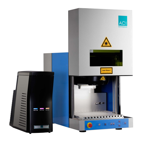
Description Description Intended Purpose The manual workplace solution Workstation CLASSIC Fibre is characterized by its large workroom. You can mount workpieces with an area of up to 340 mm x 360 mm on its T-slot plate. Depending on the laser system and objective used, a marking field of maximum 180 mm x 180 mm is available. -
Page 18: Views Of The Device
Description Views of the Device Front side (1) Safety door (2) Viewing window (3) T-slot plate (4) Workroom (5) Control panel (6) Power switch Kl as la s sif izi er t DI N 5- 1/1 There are also additional connections in the workroom. -
Page 19: Rear Side
Description Rear side (1) Connections rear side (2) Extraction connector (3) Type plate (4) Fiber laser cable... -
Page 20: Technical Specifications
Objective Marking field nent height CLASSIC Fibre F-Theta 163 150 mm 110 mm x 110 mm CLASSIC Fibre XL F-Theta 163 270 mm 110 mm x 110 mm F-Theta 254 143 mm 180 mm x 180 mm Maximum working areas... -
Page 21: Laser Protection Screen
Description Laser protection screen Width x Height: 276 mm x 200 mm Specification: Depends on the type of laser device used Yb:fibre laser 1040 - 1100 nm D AB6 IR AB6 (DIN EN 12254) >1100 - 1185 nm D AB6 IR AB6 (DIN EN 12254) >1185 - 1215 nm D AB5 IR AB5 (DIN EN 12254) The listed laser protection screen specifications are the minimum requirements for the... -
Page 22: Operating Conditions
Description Operating conditions Working temperature: 15°C - 35°C Air humidity (rel.): 30% - 85%, not condensing Weight without laser 45 kg • Options Workpiece holders • Laser extraction unit • Rotary module • Foot switch Scope of Delivery • Workstation, •... -
Page 23: Installation
Installation Installation Unpacking (1) Workstation (4) Pallet (2) Lid (5) Fixing screws (3) Carton... -
Page 24: Setting Up
Lift the pallet (4) bearing the workstation (1) with a suitable device (such as a lifting truck), and remove the fixing screws (5). NOTICE The Workstation CLASSIC Fibre weighs 45 kg. Place the device on a suitable flat surface. Remove the accessories from the workroom, and put them in a safe place. -
Page 25: Assembly
Installation Assembly 5.3.1 Connections Rear side (1) Power switch (2) Power input module with fuse module (3) Laser I/O (4) USB interface to the PC (5) Interlock (6) Extraction (7) External start Workroom (1) Power 2 (2) Power 1 (3) Laser I/O (4) Adapter for rotary module... -
Page 26: Laser Marking Device Assembly
Installation 5.3.2 Laser Marking Device Assembly Fasten the laser marking unit to the mounting panel of the workstation, following the laser marking unit’s operating instructions. Connect the three connecting cables - laser interface cable, - power cable, - USB cable, to the laser marking device. -
Page 27: Connection Of Supply Cable And Fiber Laser Cable
Installation 5.3.5 Connection of Supply Cable and Fiber Laser Cable The supply cable and the BDO fiber laser cable between the laser head and supply unit must be connected. (1) Mounting block (2) Workstation real wall (3) Front cover plate, 2-part (4) Rear cover plate Unscrew the 2-part front cover plate, the rear cover plate and the mounting block. -
Page 28: Connection With Pc
Installation Screw the mounting block, the rear cover plate and the 2-part front cover plate in fin- ger tight. Ensure that the cables are not pinched in the process. 5.3.6 Connection with PC Connect the USB interface on the workstation to the PC. Checking the Installation CAUTION RISK OF PROPERTY DAMAGE. -
Page 29: Operation
Operation Operation Operating and Display Elements Control panel In the setting-up mode, various functions may be controlled using the buttons on the operator control panel. (1) Emergency stop button (4) Rotation left/right (2) Light on/off (5) Z axis top/bottom (3) Focus on/off (6) Open/close door NOTICE Only the buttons enabled will be lit, depending on the current settings. -
Page 30: Emergency Stop Button
Operation Emergency stop button The emergency stop button is located on the left-hand side of the operating panel on the front of the device. Stop the machine by pressing the emergency stop button whenever a situation arises which poses danger to the operating personnel or the device system. The emergency stop button stops movements of the door and axes, and breaks the laser safety circuit. -
Page 31: Start
Operation Start NOTICE Keep to the switching sequence on each start. Start the laser marking device in accordance with the operating instructions. Activate the power switch for the workstation. Press the Close door button to initialize the workstation. When the workstation is started up for the first time, you need to enter the settings for the external units in the software. -
Page 32: Fault Finding
Operation Fault Finding Problem/Fault Possible cause Elimination Cut off Emergency stop button pressed Releasing the emergency stop button Not referenced Cover not initialised/referenced Press the Door close button Offline Driver not installed Install driver Device not listed in the Device manager Check the USB plug of the operating system Device not switched on... -
Page 33: Maintenance, Repair, Care
Maintenance, Repair, Care Maintenance, Repair, Care All maintenance and repair work must be performed exclusively by the manufacturer. We recommend you to perform maintenance at intervals of 24 months. The right to claim under warranty is lost as soon as third parties work on or modify the de- vice. -
Page 34: Scrap Disposal
Scrap Disposal Scrap Disposal ENVIRONMENT Protect the environment! For a fee, the customer will accept return of the laser device and dispose of it properly in a manner that is environmentally compatible. Environmentally sensible disposal of electrical and electronic equipment! Electrical and electronic equipment contains valuable materials that should be supplied to recycling or recovery. -
Page 35: Appendix
Appendix Appendix Wiring Diagram Connectors in working area Connectors on the rear panel power 1 power 2 CON7 cable connector according to IEC130-9 binder series 680 receptacle type "B" OUT1 (USC) OUT1 (USC) upstream to PC OUT2 (USC) OUT2 (USC) cable connector according to IEC130-9 +24V +24V... - Page 36 Appendix Components inside wall Components mounting plate rear wall fuse holder power 2 ext. start PCB Micos adapter 30390058 USB 2.0 upstream interlock laser IO power input DSub9F power 1 exhauster Connection laser interface Connection laser I/O interior DSub37M FSub9F not PLe INTL2 OUT1...
-
Page 37: Drawing Of The T-Slot Plate
Appendix Drawing of the T-Slot Plate 14.5 A (2 : 5) -
Page 38: Assembly Dimensions
Appendix Assembly Dimensions Workstation CLASSIC Fibre... - Page 39 Appendix Workstation CLASSIC Fibre XL...
-
Page 40: Drawing Of The Axis Stroke
Appendix Drawing of the Axis Stroke Workstation CLASSIC Fibre: x = min. 200 mm, max. 350 mm Workstation CLASSIC Fibre XL: x = min. 320 mm, max. 470 mm... -
Page 41: Illustration Of The Rotary Module
Appendix Illustration of the Rotary Module 176.1 ø... -
Page 42: Illustration Of The Working Areas
Marking field = working area F-Theta 163 110 mm x 110 mm F-Theta 254 180 mm x 180 mm Maximum component height Workstation CLASSIC Fibre F-Theta 163 150 mm Workstation CLASSIC Fibre XL F-Theta 163 270 mm F-Theta 254 143 mm... -
Page 43: Ec Conformity Declaration
EN 349:1993+A1:2008 EN 60204-1:2006+A1:2009 EN 60825-4:2006+A1:2008+A2:2011 Representative for compiling technical documents: Mirko Wunderlich, Steinbrüchenstraße 14, 99248 Grammetal OT Nohra Signed on behalf of the manufacturer by: Nohra, 01.08.2019 ACI Laser GmbH Mirko Wunderlich, Geschäftsführer Steinbrüchenstraße 14, 99428 Grammetal OT Nohra... - Page 44 Appendix...
-
Page 45: Index
Index Index Air humidity (rel.) ............................22 Buttons, active ............................29 Care ..............................14 CE symbol ..............................7 Cleaning ..............................33 Component height ............................. 20 Connection values ............................. 21 Connection with PC ........................... 28 Connections ............................... 25 Rear side ............................19 Workroom ............................ - Page 46 Index Assembly ............................26 Connector ............................19 Fault finding ............................... 32 Fiber laser cable ............................19 Focus finder function ..........................20 Focus on/off ............................... 29 Foot switch ..............................22 Frequency range ............................16 Front side view ............................18 Fuse ............................. 16 Height adjustment .............................
- Page 47 Index Maintenance ............................14 Manufacturer .............................. 16 Manufacturer’s address ..........................11 Marking field .............................. 20 Mounting area of the T-slot plate ....................... 20 Open/close door ............................29 Operating conditions ..........................22 Operating voltage ..........................16 Operation ............................14 Options ..............................22 Positioning and repetition accuracy ......................
- Page 48 Index Safety instructions ............................. 12 Scope of delivery ............................22 Scrap disposal ............................34 Serial number ............................16 Setting-up mode ............................29 Start up ..............................13 Switching sequence ..........................31 Technical specifications ..........................20 T-slot plate ..............................18 Drawing ............................37 Mounting area ..........................
- Page 50 Operating Instructions for Workstation CLASSIC Fibre/Workstation CLASSIC Fibre XL Article number: 10002189 Version: EN 08/2019-03 ACI Laser GmbH Steinbrüchenstraße 14 D-99428 Grammetal OT Nohra Phone: +49 3643 4152-0 Fax: +49 3643 4152-77 info@ACI-Laser.de www.ACI-Laser.de Mark your territory...
Need help?
Do you have a question about the CLASSIC Fibre and is the answer not in the manual?
Questions and answers