Advertisement
Quick Links
File No.:
Version:
Shenzhen Rakinda
Technologies Co.,Ltd.
V1.0
Confidential
Face Recognition Thermal
Imaging Temperature
File Name
Date
Apr., 23, 2020
Measuring Device
F2-H Manual
Face Recognition Thermal Imaging Temperature Measuring Device
F2-H Manual
Shenzhen Rakinda Technologies Co.,Ltd.
Copyright
Advertisement

Summary of Contents for RAKINDA F2-H
- Page 1 File No.: Version: Shenzhen Rakinda Technologies Co.,Ltd. V1.0 Confidential Face Recognition Thermal Imaging Temperature File Name Date Apr., 23, 2020 Measuring Device F2-H Manual Face Recognition Thermal Imaging Temperature Measuring Device F2-H Manual Shenzhen Rakinda Technologies Co.,Ltd. Copyright...
-
Page 2: Application Field
Face Recognition Thermal Imaging Temperature Measuring Device F2-H Manual Application Field F2-H is suitable for office areas, hotel, office buildings, schools, shops, communities, public services and management projects. Features Dynamic detection, solve the deception of photos on various carriers ... -
Page 3: Product Specification
Support HTTP interface connection; Support display configuration; Support identification distance configuration Product Specification Face Recognition Temperature Measure all-in-one Machine Product model F2-H Main function Face recognition temperature measurement Indoor , semi-outdoor environmen Characteristics Color Silver Type Infrared... - Page 4 WIFI Comply with IEEE802.11b / g / n standard (2.4G) method Face Support Identification Support, optional IC card Method RJ45 interface Support 10/100 Mbps Input \ output Power supply interface DC12V-2A interface Power Adapter DC12V-2A Operating -20℃~60℃ temperature Working 20%~90% (non-condensing) humidity Environmental Static...
- Page 5 Power < 0.3w consumption 32*32 Real-time temperature output Pixel Measurement I + 0.5 ℃ accuracy Measuring Basic 0.3 ~ 1.0m distance Parameters WIFI 2.4G 802.11b/g/n Bluetooth BluetooH4.0 Attention: The following only describes the serial temperature measurement module No description about I²C interface temperature measurement module, the shape is rectangular forbidden to use under strong light and direct sunlight;...
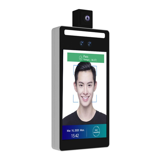
- Page 6 Wall Mounting Type Product Picture...
- Page 7 Wall-mounted version shape and size(275.8mm*123.8mm*30.2mm)...
- Page 8 Indication of Appearance and Wiring Instructions The front part of the access control machine...
- Page 9 Access control wall-mounted version-wiring instructions...
- Page 10 Installation Steps Installation of access control wall-mounted version Description of the size of the wall bracket; Note: The product packaging comes with 86 boxes of machine screws and plastic expansion screws;...
- Page 11 Description of the installation location of the wall bracket;...
- Page 12 Fixing method of hanging bracket and product terminal Note: Use three set screws M3 * 5 to fix the terminal. There are matching screws in the package.
- Page 13 Wiring operation instructions (take the turnstile wiring as an example, other wiring can take this as reference) (1) Strip the signal wire (use a wire stripper and other tools) to expose the metal wire, about 5mm, if possible, add solder, as shown in the figure; (2) Loosen the screws at each corresponding interface, insert the metal wire end into the hole, tighten the screws to fix, and do a tensile test after locking to ensure stability, as shown in the figure;...
- Page 14 Supply power to electromagnetic lock, and Magnetic lock power also can supply power to Uface host at the supply (optional) same time (If you already have it, you don't need more) Network cable (optional) Several Used to arrange Ethernet and other wiring Network cable pliers,...
-
Page 15: Installation Notice
2. Schematic diagram of magnetic door system wiring: Installation Notice: 1. During wiring, if the 12V power supply line of the host does not use the "special power supply extension line" and the distance is long, the cable equivalent resistance will be too high, then it is possible to occur: terminal insufficient voltage (≤11V), repeated restart of the host, and crash phenomenon。... - Page 16 The extension of the power cord (weak current part) should not exceed 3 meters, otherwise it will cause insufficient power supply to the host, and abnormal phenomena such as repeated restarts and crashes. If the power supply is far away from the device, the power cord (strong electric part) can be extended.。 If you use other adapters, such as 9V and 1A, insufficient voltage and low current will cause the device to restart repeatedly.
Need help?
Do you have a question about the F2-H and is the answer not in the manual?
Questions and answers