Advertisement
Quick Links
Advertisement

Subscribe to Our Youtube Channel
Summary of Contents for Stewart Filmscreen CVM
- Page 1 O W N E R S M A N U A L CVM Control Producers of Professional Projection Screens...
- Page 2 Printed in U.S.A. ©2019 Stewart Filmscreen Corporation Stewart Filmscreen reserves the right to make changes to the product specified in this document. Sizes and specifications subject to change without notice at Manufacturer’s discretion. From time to time, this document is updated. Current versions of documentation are posted on the Stewart Filmscreen website at:...
-
Page 3: Table Of Contents
CVM Control O W N E R S M A N U A L Contents About CVM Keypads Presets STI Inputs CVM Inputs Appendix Commands... -
Page 4: About Cvm
If you are using serial or IP control, this blinking LED will be green At this time you can begin to operate the CVM control system For enhanced testing, control and bi- directional feedback, use the Pilot application software thru the IP port... -
Page 5: Keypads
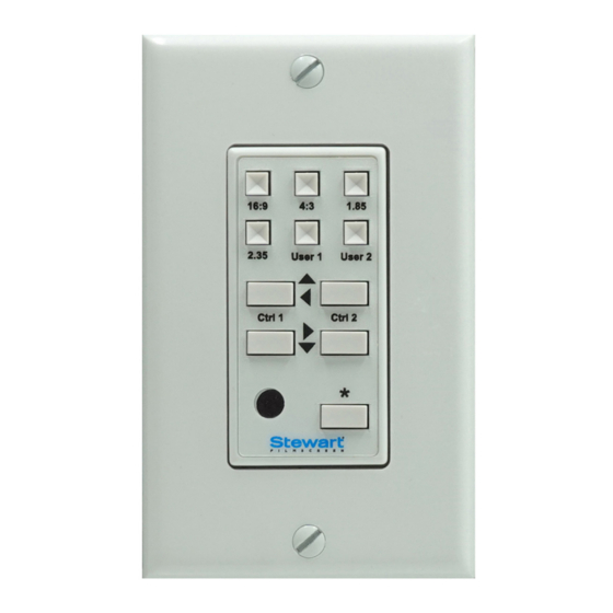
You will find the four long horizontal buttons on the keypad to manually operate the motor panels or screen Ctrl 1 operates Channel A of the CVM This will typically be a screen, left panel or top horizontal panel Ctrl 2 operates Channel B of the CVM which is typically a right panel or bottom horizontal panel... -
Page 6: Presets
If you press & release this button, you will now have independent control of the vertical side panels (CVM slave board) If you position these panels and wait a few seconds, the CVM will auto- matically return the keypad to operate the Master board (top & bottom horizontal panels) The Master board operates the top &... - Page 7 To store or overwrite a preset, move the screen or panels to a desired position and then press and release the blue Program button Next press whichever preset you want and now that new setting will be recorded CVM Control...
- Page 8 We suggest using Standard Ethernet cables for this purpose and for excessive runs, shielded cable will yield best results The CVM’s IP port is a standard RJ-45 port located on the far right end of the board If you will be using serial communication, use the...
-
Page 9: Sti Inputs
#2 When a second trigger signal is sent, the system moves over to preset # 1 The operating range of the CVM trigger input is +3 to + 12 VDC covering just... -
Page 10: Cvm Inputs
High Voltage motor lead connections: White = Neutral, Black – Down, Red – Up Can be shortend if needed AC power input: White – Neutral, Black – Hot Line Blue blinking LED indicates wired CVM keypad connected & operating the system Green blinking LED signifies serial or IP control Stewart Filmscreen... - Page 11 IP control from your network is easily obtained by connecting a standard RJ-45 Ethernet cable from your network switcher to the IP port on the CVM board You can use Hyper Link, Putty or Pilot as the operating program At that time the CVM will auto assign its IP address and you can begin sending the Syntax control commands These commands are located on page 13 for your convenience To find the CVM IP address on your PC or laptop –...
-
Page 12: Appendix
APPENDIX Stewart Filmscreen... -
Page 13: Commands
COMMANDS (SERIAL) Serial Communication Parameters Set up your serial communication software (from your AMX, Crestron, or other automation system) with the following serial communication parameters These parameters cannot be changed within the CVM or IBT-100 serial converter Baud rate 19200... - Page 14 Shows Ch A motor’s position as % #1 1 2 MOTOR POSITION=?; Shows Ch B motor’s position as % #1 1 3 MOTOR POSITION=?; Shows Ch C motor’s position as % #1 1 4 MOTOR POSITION=?; Shows Ch D motor’s position as % Stewart Filmscreen...
- Page 15 1161 W. Sepulveda Blvd., Torrance CA 90502 USA 800.762.4999 Tel: 310.784.5300 Fax: 310.326.6870 Email: request@stewartfilmscreen.com ©2019 Stewart Filmscreen. Specifications are subject to change without notice.
Need help?
Do you have a question about the CVM and is the answer not in the manual?
Questions and answers