Table of Contents
Advertisement
Quick Links
DP/CAN Coupler
PRPFIBUS DP for CAN-Bus Coupler
for CAN Layer 2
700-651-CAN01
Manual
Edition 5 / 25.06.2009 HW1 & FW 1.5X and higher
Order number of manual: 900-651-CAN01/en
Systeme Helmholz GmbH
Hannberger Weg 2
D-91091 Großenseebach
Phone: +49 9135 7380-0
Fax: +49 9135 7380-110 l E-mail: info@helmholz.de
Internet:
www.helmholz.de
Advertisement
Table of Contents

Summary of Contents for Helmholz 700-651-CAN01
- Page 1 CAN Layer 2 700-651-CAN01 Manual Edition 5 / 25.06.2009 HW1 & FW 1.5X and higher Order number of manual: 900-651-CAN01/en Systeme Helmholz GmbH Hannberger Weg 2 D-91091 Großenseebach Phone: +49 9135 7380-0 Fax: +49 9135 7380-110 l E-mail: info@helmholz.de Internet: www.helmholz.de...
- Page 3 (photocopy, microfilm, or other method) without the express written permission of Systeme Helmholz GmbH, not even for use as training material, or using electronic systems. All rights reserved in the case of a patent grant or registration of a utility model or design.
- Page 4 Revision history of this document: Edition Date Revision Notice about consistent data extended 18.05.2009 29-bit protocol implemented...
-
Page 5: Table Of Contents
Contents Safety Information General Restriction of access Information for the user Use as intended Avoiding use not as intended! Installation and Mounting Vertical and horizontal mounting System Overview Application and function description Connections LED displays DIP switches Items supplied Accessories Configuration (CAN Layer 2) Installing and parameterizing the device Defining the I/O address area in the PLC... - Page 6 5.4.2 29-bit protocol 5.4.3 Receive Object Service Transmit Object 5.5.1 11-bit protocol 5.5.2 29-bit protocol PLC diagnostics Appendix Technical Data Pin assignment Further Documentation DP/CAN Coupler...
-
Page 7: Safety Information
Safety Information Please observe the safety information given for your own and other people's safety. The safety information indicates possible hazards and provides information about how you can avoid hazardous situations. The following symbols are used in this manual. Caution, indicates hazards and sources of error Gives information Hazard, general or specific Danger of electric shock... -
Page 8: Restriction Of Access
Restriction of access The modules are open equipment and must only be installed in electrical equipment rooms, cabinets, or housings. Access to the electrical equipment rooms, barriers, or housings must only be Only authorized persons must have access to the possible using a tool or key and only permitted to personnel modules! having received instruction or authorization. -
Page 9: Installation And Mounting
Installation and Mounting The DP/CAN 300 coupler must be installed according to VDE 0100 IEC 364. Because it is an “OPEN type” module, you must install it in a (switching) cabinet. Ambient temperature: 0 ºC – 60 ºC. Before you start installation work, all system components must be disconnected from their power source. -
Page 10: System Overview
System Overview Application and function description The DP/CAN coupler from System Helmholz GmbH allows you to connect any CAN stations to the PROFIBUS DP. The DP/CAN coupler must be parameterized as a PROFIBUS station in the Hardware Configurator. The necessary GSD files are supplied with the device. -
Page 11: Connections
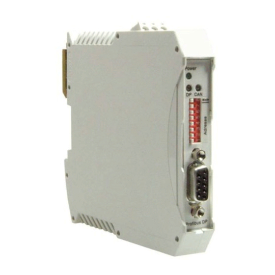
Connections PROFIBUS 9-way Sub-D socket: PROFIBUS DP Data line B VP (power supply for terminating resistors) Data line A 3-way CAN connector (no terminating resistor): CAN High CAN-GND CAN-Low 3-way power supply: LED displays The three LEDs on the front of the module inform you about its operating state. -
Page 12: Items Supplied
Items supplied DP/CAN Coupler Layer 2 700-651-CAN01 incl. 2 x 3-pin connector for CAN bus and 24V power supply CS with GSD files and instructions Accessories Manual, German/English 900-651-CAN01 CAN bus plug connector 700-690-0BA11 CAN bus plug connector with cable connector 700-690-0BB11... -
Page 13: Configuration (Can Layer 2)
Having done that you will find the DP/CAN coupler in the hardware catalog under ‘Additional FIELD DEVICES / IO / Helmholz.’ You can now drag and drop “DP/CAN coupler L2 V2h” or “DP/CAN coupler L2 V2 29B” onto a PROFIBUS network you have already set up. - Page 14 You can assign a station address to the slave here. DP/CAN Coupler...
- Page 15 The DP/CAN coupler is supplied with the necessary information with the parameterization frame from the master on start-up about the CAN frames to be processed. The following CAN parameters are defined here: CAN baud rate Cyclic transmission time of the Transmit Obect (if required) Number of receive and transmit messages CAN baud rate:...
-
Page 16: Defining The I/O Address Area In The Plc
Defining the I/O address area in the PLC Once the basic parameters of the CAN bus have been defined all data elements must be shown in the I/O area of the CPU. The first 6 elements must always be at the beginning of the list in the defined sequence. -
Page 17: Consistent Data
Consistent data All data elements are defined as consistent data. This prevents inconsistencies within the SDO and PDO data. The addresses of the data elements can be located in the cyclic process image or All CAN messages are outside the cyclic process image. If the data is outside the cyclic defined as consistent process image, access must be performed with the peripheral data areas in the... -
Page 18: Parameterizing The Receive Object
Each transmit or receive object can be defined for exactly one CAN message. The length of the CAN message corresponds to the size of the DI/DO object. The CAN ID is defined in the parameter set. Parameterizing the Receive Object The Receive Object must also be parameterized if it is to be used. -
Page 19: 29-Bit Protocol
4.6.2 29-bit protocol In order to receive any CAN frames with the Receive Object the upper 26 bits of the CAN identifier are first filtered with a mask (acceptance mask) and then compared with a predefined value (acceptance code). If this comparison is positive, the CAN frame is entered in the Receive FIFO and the PLC is released. -
Page 20: Programming (Can Layer 2)
Programming (CAN Layer 2) Data exchange When the master has detected that parameterization and configuration is successfully completed without errors at the end of the start-up phase and the PLC has been started, the DP/CAN coupler can transmit and receive frames via CAN. Handshake bits The 5 bytes of the HANDSHK_IN area signal the receipt of CAN messages via the Receive Object and the DI objects. -
Page 21: Transmit And Receive Objects
The 5 bytes of the HANDSHK_OUT area are used to transmit the transmit objects and the Transmit Object. The bits always initiate transmission of the message when the bit is inverted (toggle bit). Byte Function Send frame for Transmit Object Send frame for transmit object 1 Send frame for transmit object 2 Send frame for transmit object 3... -
Page 22: Receive Object
Receive Object If a frame which corresponds to the parameterized acceptance mask of the Receive Object is received the frame is transferred to the area of the Receive Object. 5.4.1 11-bit protocol Byte Content of Receive Object: Len + RTR + HighByte CAN identifier LowByte CAN identifier Data byte 1 Data byte 2... -
Page 23: Receive Object Service
Byte 0 Data length unused Byte 1 Byte 2 unused High Word CAN identifier (13 bits) Byte 3 Byte 4 Low Word CAN identifier (16 bits) The receipt of a new frame is recognized by the inversion of bit 0 in byte 0 of the HANDSHK_IN area. -
Page 24: Transmit Object
Transmit Object Any number of messages can be sent via the Transmit Object (TrObject). 5.5.1 11-bit protocol Byte Content Transmit Object Len + RTR + HighByte CAN identifier LowByte CAN identifier Data byte 1 Data byte 2 Data byte 3 Data byte 4 Data byte 5 Data byte 6... -
Page 25: 29-Bit Protocol
5.5.2 29-bit protocol Byte Content Transmit Object Len + RTR HighByte HighWord CAN identifier LowByte HighWord CAN identifier HighByte LowWord CAN identifier LowByte LowWord CAN identifier Data byte 1 Data byte 2 Data byte 3 Data byte 4 Data byte 5 Data byte 6 Data byte 7 Data byte 8... - Page 26 Activate request LADDR Diagnostic address of DP slave - hexadezimal RetVal Error code or actual length of data in RECORD RECORD ANY pointer to the target area for the input buffer in the PLC. The data are copied from the module into this area.
-
Page 27: Appendix
Appendix Technical Data Order number DP/CAN Coupler 700-651-CAN01 Dimensions 114 x 18 x 108 mm (LxWxH) Weight Approx. 120 g CAN interface Type: ISO/DIN 11898-2, CAN high speed physical layer Transmission rate: 10 kbps to 1Mbps Protocol: CAN 2.0A/B (11 / 29 bits) -
Page 28: Pin Assignment
Pin assignment PROFIBUS 9-way Sub-D socket: PROFIBUS DP Data line B VP (power supply for terminating resistors) Data line A 3-way CAN connector (no terminating resistor): CAN High CAN-GND CAN-Low 3-way power supply: Further documentation Internet: www.can-cia.org CAN Specification 2.0, Part A & Part B DP/CAN Coupler... - Page 29 Notes DP/CAN Coupler...
Need help?
Do you have a question about the 700-651-CAN01 and is the answer not in the manual?
Questions and answers