Table of Contents
Advertisement
Quick Links
Advertisement
Table of Contents

Summary of Contents for BART-TECH 3D BT1.2
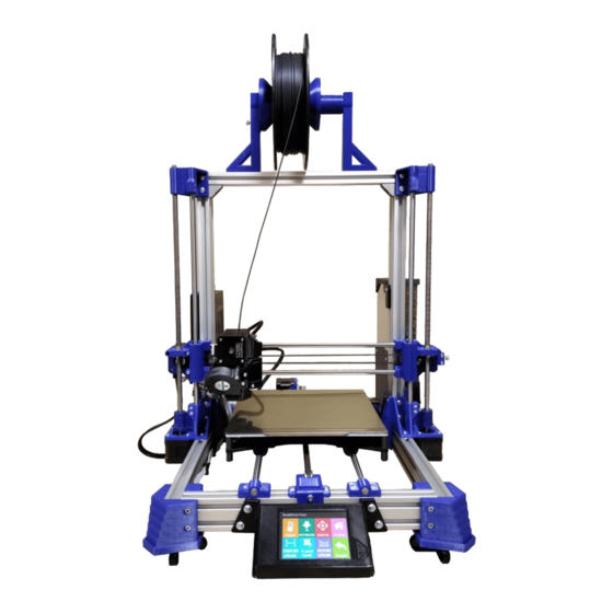
- Page 1 FDM 3D printer - BT1.2 model Operating Manual...
-
Page 2: Table Of Contents
Operating Manual for 3D Printer BT1.2 CONTENT 1. Introduction 2. Technical specifications Device description Technical specifications Description of individual parts Package Contents 3. Safety instruction Operator's obligations Electrical equipment operation Personnel without professional electrical qualification Electrical equipment Disposal of the product and its parts Operator safety instructions 4. -
Page 3: Introduction
Operating Manual for 3D Printer BT1.2 1. Introduction This operating manual contains device technical data, data and instructions for its assembly, as well as information concerning device operation and commissioning. However, the manual could not fulfil its aim if its contents are not familiar to those who operate and maintain the device. -
Page 4: Technical Specifications
The extruder nozzle is tightened by heat. The BT1.2 3D printer is designed as a single-purpose device for melting and controlled plastic lamination - a process also called FDM (Fused Deposition Modelling or FFF-Fused Filament Fabrication), and is a common 3D printing technology. -
Page 5: Description Of Individual Parts
Operating Manual for 3D Printer BT1.2 2.3 Description of individual parts Filament spool holder Trapezoidal movement Aluminum frame screws Control unit MKS GEN L V1.0 Z-axis guide DC 12V power supply rods USB connector (PC connection) Y-axis motor X-axis motor... - Page 6 Operating Manual for 3D Printer BT1.2 Printhead - EXTRUDER filament feed wheel motor E filament pressure wheel pressure door ventilator FAN1 compression spring ventilator FAN2 cooler heatblock heatbreak blowing nozzles temperature sensor hole nozzle heater hole adjustment screw for the pressure force on...
-
Page 7: Package Contents
Operating Manual for 3D Printer BT1.2 2.4 Package contents • instructions for use and installation • completely assembled lower frame including cables… 1 piece • display including cover, brackets and connecting material… 1 piece • completely assembled X axis including extruder and cables… 1 piece •... -
Page 8: Safety Instruction
Operating Manual for 3D Printer BT1.2 3. Safety Instructions Using this device in any way other than that specified by the manufacturer is contrary to its purpose! Any arbitrary changes made to this device without the manufacturer's permission void the manufacturer from any liability for consequential damage or injury! When working, follow the safety instructions to avoid risk of injury to either yourself or others around you. -
Page 9: Electrical Equipment
Operating Manual for 3D Printer BT1.2 cause of the danger themselves must take measures to prevent or reduce the risk of injury, fire or other hazards. ➢ electrical appliances must be safely disconnected from the power supply before moving 3.3 People without professional electrical... -
Page 10: Operator Safety Instructions
Operating Manual for 3D Printer BT1.2 3.6 Operator Safety Instructions (the device operator must follow these instructions) THE EQUIPMENT'S ELECTRICAL PARTS MUST NOT BE RINSED WITH WATER! ➢ Safety elements must always be kept in perfect condition ➢ Keep the device safety markings legible ➢... -
Page 11: Printer Assembly And Connection Instructions
Operating Manual for 3D Printer BT1.2 4. Printer assembly and connection instructions 4.1 Equipment construction assembly (mechanical part) Overview of the main assembly steps: 1. fasten both aluminium profiles 2. slide both guide rods into the brackets 3. install the x-axis 4. - Page 12 Operating Manual for 3D Printer BT1.2 Slide the profile in until it is in contact with the opposite profile. Hold down and gradually tighten all the bolts in the order numbered in the picture above. The same applies for both sides.
- Page 13 Operating Manual for 3D Printer BT1.2 Place the assembled X-axis with sliding bearings on the mounted guide rods. Hold the axis, do not let it fall down by itself! Hold the X axis raised and turn the movement bolt into the brass nut. Carefully lower the bolt to the motor coupling, where...
- Page 14 Operating Manual for 3D Printer BT1.2 Loosen these bolts before installing the bracket. corner connectors location Put the upper part of the frame on, put on the profile and check that the entire surface is seated correctly on both sides.
- Page 15 Operating Manual for 3D Printer BT1.2...
- Page 16 Operating Manual for 3D Printer BT1.2 tighten 4 M4 bolts with T-nuts...
-
Page 17: Connection (Electrical Part)
Operating Manual for 3D Printer BT1.2 Connection (electrical part) Overview of the main steps with concern to the control board connection: 1. 12V voltage source 2. heated pad (heating, temperature sensor TB) 3. extruder (motor E, heating, temperature sensor TH, ventilators FAN1 and FAN2) 4. - Page 18 Operating Manual for 3D Printer BT1.2 Power supply connection to the control board gradually insert the supply cable from the source into the lower cable holders (plastic lugs). Connect both contacts to the terminal block, carefully tighten with a flat-blade screwdriver and check the tightness by pulling.
- Page 19 Operating Manual for 3D Printer BT1.2 Heated pad connection The printing pad wiring harness has heated contacts (red + black) and a temperature sensor connector on the black wires. There is a reinforced brace in the cable harness. Connect both contacts to the "HBED" terminal block, carefully tighten with a flat-blade screwdriver and check the tightness by pulling.
- Page 20 Operating Manual for 3D Printer BT1.2 Extruder connection FAN2 connector – shorter cable temperature sensor connector trysky end of extruder FAN1 connector harness – longer cable extruder heating contacts Note: There is a reinforcing brace in the cable motor (heater) harness.
- Page 21 Operating Manual for 3D Printer BT1.2 Stepper connection motors Limit switch connection X, Y, Z1, Z2 X, Y, Z1, Z2 Ends of the cables with connectors are marked with description of the relevant axe (X, Y, Z1, Z2). LCD Connection...
- Page 22 Operating Manual for 3D Printer BT1.2 Fastening output cables Ensure that all cables are fixed with cable ties. Cut off the cable tie excess. Connection of "FAN0" ventilator in the housing cover ventilator FAN 0 Cabinet cover with ventilator Connect FAN0 connector to a free 12V socket on the board. Close the cover with the ventilator and fix it on (4x Allen screw...
-
Page 23: Commissioning
Operating Manual for 3D Printer BT1.2 4.3 Commissioning After reading these instructions, installation and correct wiring: 1. place the printer on anti-vibration pads on a flat surface 2. check the main switch position - it must be in the off position "0"... -
Page 24: Starting Printing - Programme (*.Gcode)
Operating Manual for 3D Printer BT1.2 5. Printing 5.1 Starting printing - programme (*.gcode) The device is only able to run (read) programmes (files) in the "gcode" format, generated by special software (called "slicer"). This software is able to generate a programme for controlling the device from the part model that we want to print. - Page 25 Operating Manual for 3D Printer BT1.2 Start and stop the programme on the TFT32 control panel 3. select the desired .gcode file 1. basic (default) screen after 2. press the "PRINT" icon startup. 3. The programme starts after 4. when the programme starts, a confirming "Confirm".
-
Page 26: Pad Calibration
Operating Manual for 3D Printer BT1.2 5.2 Print pad calibration After the device has been completely assembled, the print pad must be calibrated. This step is very important and fundamentally affects the first layer's adhesion to the surface, therefore the print quality and the overall result. For this reason, we recommend that you are very careful when performing this operation. - Page 27 Operating Manual for 3D Printer BT1.2 Electronic printing pad calibration - unevenness mapping - "MESH BED LEVELLING" The printer software allows you to adjust the nozzle height during printing according to the pad's unevenness. However, this unevenness must be measured in advance and stored in the printer's memory. Follow the steps below.
- Page 28 Operating Manual for 3D Printer BT1.2 Introduction of a new printing string (filament) Extruder: this is the part of the equipment where the plastic is melted. The filament is pushed in by the motor, the drive and the pressure feed gear. This system is called a "Direct-Dual drive". The extruder is designed for filaments with a diameter of 1.75 mm.
-
Page 29: Restarting The Printer - Reset
Operating Manual for 3D Printer BT1.2 5.4 Restarting the printer – RESET You will need to restart the printer either due to an emergency stop, or if the printer stops for another reason and requires a restart. Usually thermal protection, e.g., when you press a cold steel plate on a pad that has just been heated and sudden temperature fluctuations occur. -
Page 30: Maintenance
Operating Manual for 3D Printer BT1.2 Maintenance 6.1 Moving parts Only carry out maintenance on moving parts when the device is switched off and disconnected from the mains. Due to the fact that the moving parts are stressed by extremely small forces, the device does not require special regular maintenance. - Page 31 Operating Manual for 3D Printer BT1.2 Heating the pad The "EXTRUDE1" button switches to "BED" and vice versa when pressed. Set the temperature with the "+" and "-" buttons This menu is for both heating the pad and heating the nozzle.
-
Page 32: Printhead (Extruder)
Operating Manual for 3D Printer BT1.2 6.3 Printhead (extruder) Before every print, we recommend wiping the heated nozzle (to approx. 220°C) with a cotton cloth to remove the rest of the molten filament. Use leather work gloves for this operation. Take extra care - risk of burns! Otherwise, the print head does not usually require specific maintenance. - Page 33 Operating Manual for 3D Printer BT1.2 Nozzle replacement procedure Take extra care during this procedure. This is handling a hot part. Therefore, only handle hot parts with the appropriate tools! Protective work aids - leather gloves - are recommended. 1. Remove FAN2 ventilator, nozzle blower and silicone cover (assembly see p.6)
- Page 34 Operating Manual for 3D Printer BT1.2 BART-TECH 3D s.r.o. Bohdalov 304 592 13 Bohdalov tel: +420732448895 Publication date: e-mail: info@bart-tech3d.cz 16.9.2020 www.bart-tech3d.com...
Need help?
Do you have a question about the BT1.2 and is the answer not in the manual?
Questions and answers