Table of Contents
Advertisement
Quick Links
MOUNTING INSTRUCTIONS: TJ1107xEDR TOP JAMB Series
Electro-Magnetic Lock for In-Swing Doors
READ THOROUGHLY BEFORE INSTALLING
IMPORTANT: Handle electro-magnets and armatures carefully. Any damage to the mating surfaces may significantly
reduce holding efficiency.
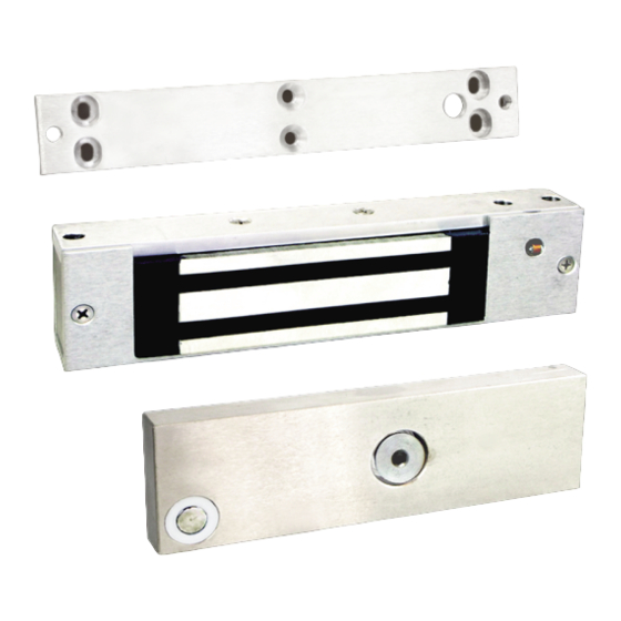
The TJ1107 Series Electro-magnet assembly mounts firmly and rigidly to the header using an L-Bracket. The armature is
held by the Z-Bracket which mounts to the face of the door. Special hardware is used to allow the armature to automatically
align with the face of the electromagnet for maximum holding force when the magnet is energized.
A 2-1/4" wide flat surface is required to mount the TJ1107 series magnet and L-Bracket assembly (see Figure 1). For uneven
or irregular surfaces, the use of shims or filler plates may be required. See the Application Bulletin (attached) for diagrams of
typical door configurations and part numbers for spacers, filler blocks, shims and mounting brackets required for each type of
installation
For hollow metal door and similar installations requiring drilling and tapping, the material thickness should be at least 1/8".
Sheet metal screws may be used for wood doors and clad doors. For thinly clad doors or wooden doors without sufficient
solid backing, a reinforcing plate may be required.
Before starting, make sure the correct drill template is available for the type of installation planned. Door swing and
construction, door frame material and configuration must be considered before deciding on the proper mounting kit and
method.
STEP 1) MARK AND DRILL JAMB HEADER & INSTALL L-BRACKET
The electromagnet assembly is carried by an L-Bracket that mounts directly to the header – see Figure 1. Before drilling the
header, trial fit the bracket and magnet assembly to make sure that it will mount flush to the bottom of the header with
sufficient clearance for the door to operate without interference.
Use the supplied template to mark the door frame header for drilling. Depending on the material, size the drill bit for either
#14 Sheet Metal screws or for tapping 1/4-20 machine screws. Drill clearance hole through header for wire passage.
Break all sharp edges to prevent damage to wire insulation and potential short circuits. Use star washers with machine
screws to prevent loosening over time.
Figure 1
Page | 1
REV#0001A
For wood jambs or clad door framing,
the structure must be capable of carrying
the holding force generated by the magnet.
The use of reinforcing material or bolting
Through the header may be required.
REV#0002A
TJ1107XEDR
Advertisement
Table of Contents

Related Manuals for DORTRONICS SYSTEMS TJ1107xEDR TOP JAMB Series

Summary of Contents for DORTRONICS SYSTEMS TJ1107xEDR TOP JAMB Series
- Page 1 MOUNTING INSTRUCTIONS: TJ1107xEDR TOP JAMB Series Electro-Magnetic Lock for In-Swing Doors READ THOROUGHLY BEFORE INSTALLING REV#0001A IMPORTANT: Handle electro-magnets and armatures carefully. Any damage to the mating surfaces may significantly reduce holding efficiency. The TJ1107 Series Electro-magnet assembly mounts firmly and rigidly to the header using an L-Bracket. The armature is held by the Z-Bracket which mounts to the face of the door.
- Page 2 STEP 2) MAKE ELECTRICAL CONNECTIONS. The TJ1107xEDR electro-magnetic lock should be connected to a Class 2 power supply. Leads are connected in series for 24 volt operation (as shipped from the factory) or connected in parallel for 12 volt operation. For 12 volt operation, cut the gray wire to make 2 equal lengths, strip back the insulation 3/8”...
- Page 3 Figure 3 THRU BOLT MOUNTING IN SOLID CORE WOOD DOOR Utilizing the template Drill (4) 11/32” holes through door for knurled sex nut. Insert a 1/4-20 screw through the Z-bracket and the face of door. Hold firmly against door by pushing directly on head of screw. Insert sex nut from opposite face and assemble.
- Page 4 Figure 4 Page | 4 TJ1107XEDR REV#0002A ...
- Page 5 Page | 5 TJ1107XEDR REV#0002A ...
- Page 6 Page | 6 TJ1107XEDR REV#0002A ...
Need help?
Do you have a question about the TJ1107xEDR TOP JAMB Series and is the answer not in the manual?
Questions and answers