Advertisement
Quick Links
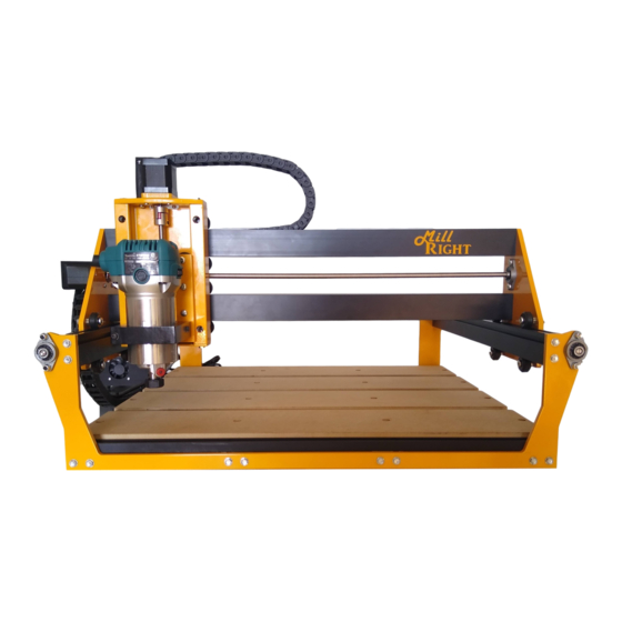
ASSEMBLY INSTRUCTIONS FOR THE MILLRIGHT CNC CARVE KING 2
Version 1.00
Note that these are instructions for the Carve King 2. For instructions on the original Carve King, see
www.millrightcnc.com/resources
Contact
support@millrightcnc.com
if you have questions.
Important safety rules for operating your MillRight CNC Carve King 2:
Never place your hands near a spinning end mill or bit.
Unplug the router before changing cutting tools.
Always wear eye and ear protection while operating your machine.
Always run a dust collector or wear a mask while performing a milling operation.
Do not leave the machine unattended while running a milling operation.
Do not operate your machine while under the influence of alcohol or drugs.
Secure long hair and loose clothing so it is not caught in spinning mechanisms.
Ensure work pieces are properly secured before running a milling operation.
Keep a fire extinguisher nearby.
Visually inspect wires prior to power up to prevent short circuits.
Note:
We recommend using a blue thread locker on any fastener not secured with a lock washer or lock nut.
Page 1 or 34
Advertisement

Related Manuals for MillRight CARVE KING 2

Summary of Contents for MillRight CARVE KING 2
- Page 1 ASSEMBLY INSTRUCTIONS FOR THE MILLRIGHT CNC CARVE KING 2 Version 1.00 Note that these are instructions for the Carve King 2. For instructions on the original Carve King, see www.millrightcnc.com/resources Contact support@millrightcnc.com if you have questions. Important safety rules for operating your MillRight CNC Carve King 2: Never place your hands near a spinning end mill or bit.
- Page 2 Building the Bed and Frame Section Parts (4) 593mm Extrusion (1) Front Frame (1) Rear Frame (5) Black Aluminum T Track (4) MDF Bed Section Hardware (16) #10x1 Self-tapping Screw (20) M5x8 Button Cap Screw (16) M5x16 Machine Screw (16) M5 Split Lock Washer (36) Drop-In T Nut Tools 3mm Hex Key...
- Page 3 Lubricate 2 #10x1 self-tapping screws. Place the screws through the holes in the bottom of the frame into the holes in the end of the right most extrusion. Use the 8mm socket to drive in the screws. Leave loose. Continue installing the #10x1 screws in the other 3 extrusions.
- Page 4 Lubricate (2) #10x1 self-tapping screws. Place screws through the holes in the bottom of the remaining frame piece into the holes in the end of the extrusion. Use the 8mm socket to drive the screws. Leave loose. Continue the process, installing the remaining extrusions.
- Page 5 Lubricate (2) self-tapping screws. Place the screws through the two holes on the frame and into the holes in the end of the extrusion. Finger tighten the screws to hold the extrusion in place. Do the same to the other end of the extrusion.
- Page 6 Gantry End Plate Assembly Parts Motor Side Gantry Plate Idler Side Gantry Plate X/Z Motor Spacer Plate Short Wire Motor Hardware Pillow Block Bearing Coupler (2) Anti-backlash Nut (2) M5 Grub Screw (in Anti-backlash nut bag) (2) M5 Jam Nut (in Anti-backlash nut bag) (4) M3x16 Machine Screw (2) M5x10 Machine Screw (4) M5x16 Machine Screw...
- Page 7 Place (2) eccentric spacers in the Idler Side Gantry Plate (top picture on previous page). Place eccentric spacers with the thin wall portion pointing to the top of the Idler Side Gantry Plate. Put a M5x30 machine screw through the v-wheel, then through the eccentric spacer.
- Page 8 Place (2) eccentric spacers into the Motor Side Gantry Plate with the thin wall of the eccentric spacer facing up. Place a M5x30 machine screw through a v-wheel, then the eccentric spacer, and secure with a M5 nylock nut. Repeat the process with a second wheel. Flip the plate. Place the coupler on the short wire motor using the X/Z Motor Spacer Plate to set the coupler to the correct position.
-
Page 9: Plate Assembly
On the motor side of the Motor Side Y Gantry Plate, place an anti-backlash nut. Using (2) M5x16 machine screws, secure the anti-backlash nut to the plate. Place both Y Gantry Plates to the side. X Plate Assembly Parts X Plate Z Bottom Plate UHMW Screw Seat Hardware... - Page 10 (2) M5x12 Button Cap (2) #10x1 Self-tapping Screw V-Wheel Kit Tools Phillips Screwdriver 8mm or 5/16” Wrench or Socket 3mm Hex Key WD40 or Other Lubricant The top of the X Plate Extrusion has a notch. The bottom is flat. Take a M5x25 machine screw and put it through a v wheel, then through a standard spacer from the v-wheel kit, then screw it into the X Plate Extrusion.
- Page 11 Place a M5x30 machine screw through the hole in the front of the X Plate Extrusion. Place an eccentric spacer on the screw. The thin part of the spacer should face the top if near the top, the bottom if near the bottom.
- Page 12 Place the Z Bottom Plate on the bottom of the X Plate Extrusion. Lubricate (2) #10x1 self- tapping screws and place them through the Z Bottom Plate into the holes at the end of the X Plate Extrusion. Tighten with the 8mm wrench. Place the X Plate Extrusion to the side.
- Page 13 Z Motor Mount Parts Z Motor Mount X/Z Motor Spacer Plate Long Wire Motor X Drag Chain Post Hardware (4) M3x16 (1) M4x12 (1) M4 Split-Lock Washer Tools Phillips Screwdriver Put the motor on the table with the cord pointing away from you.
- Page 14 Z Plate Parts Z Plate Router Mount 2 Hole Spacer 178mm Lead Screw Hardware (1) Anti-backlash Nut (2) Nylock Nuts (1) Grub Screw (in Anti-backlash nut bag) (1) M5 Jam Nut (in Anti-backlash nut bag) (1) Coupler (2) M5x25 Machine Screw (2) #10x1 Self-tapping Screw V-Wheel Kit Tools...
- Page 15 Place eccentric spacers in the (6) large holes on the Z Plate. The thin part of the eccentric spacers should face the middle of the plate. Place a M5x30 machine screw through the Z Plate, then through the eccentric spacer. Place a v-wheel on the screw and secure with a M5 nylock nut.
- Page 16 From the top of the X Plate Extrusion, thread the 178mm lead screw through the anti-backlash nut connected to the Z Plate. Continue until the lead screw is sitting in the pocket on the UHMW Screw seat. Place the coupler on the top of the lead screw. Leave loose.
- Page 17 Run the 613mm extrusions through the v-wheels on the X Plate Extrusion. The extrusion with the MillRight sticker will go up top. Make sure the extrusions are oriented as pictured. If the wheels are too tight, use the 10mm wrench to turn the eccentric spacers until the extrusions fit.
- Page 18 Lubricate (4) #10x1 self-tapping screws and place them through the Idler Side Y Gantry Plate into the holes on the end of the 613mm extrusion. Use the 8mm socket to tighten the screws. Using the 1.5mm Hex Key, loosen the set screws on the pillow block bearing.
- Page 19 Gantry to Y Rails Parts (2) 600mm Lead Screw (2) Motors (one long wire, one short wire) (2) 3 Hole Motor Spacers Hardware (2) Drop-in T Nut (2) M5x10 Machine Screw (2) M5x16 Machine Screw (4) M5x16 Button Cap Screw (6) M3x20 Machine Screws (2) M5 Washer (2) M5 Split Washer...
- Page 20 Place the Gantry onto the Y Rails as pictured. Place a V-wheel on an M5x25 machine screw, followed by a standard spacer from the V- wheel kit. Put the v-wheel into the V groove of the extrusion before tightening the screw. Screw the v-wheel into the bottom of the Gantry Y Plate.
- Page 21 Insert a drop-in T nut into the Y Extrusion near the Rear Frame as pictured. Grab a corner bracket. If it has a tabbed side and a non-tabbed side, the tabbed side will fit into the slot on the Rear Frame as pictured. It is okay if neither side has tabs. Place an M5 split lock washer on a M5x16 machine screw, place it through the corner bracket, then through the slot in the Rear Frame.
- Page 22 Place (3) M3x20 machine screws and them through the Rear Frame, through the 3 Hole Motor Spacer, into the motor. The motor wire should be pointing down and angled towards to middle of the machine. Line up the edge of the Rear Frame, the 3 Hole Motor Spacer and the motor.
- Page 23 Use the 2.5mm hex key to tighten the coupler. Use the 1.5mm hex key to tighten the pillow block bearing set screw. Repeat the process on the opposite side of the machine. Page 23 or 34...
- Page 24 Drag Chain Installation Parts Drag Chain Angle Mount X Drag Chain Bracket Y Drag Chain Post (2) Drag Chains Hardware (2) M5x8 Button Cap Screw (2) M4x12 Machine Screw (2) M3x16 Machine Screw (3) M3x8 Machine Screw (2) M5 Lock Washers (2) M4 Lock Washer (5) M3 Nylock Nuts (2) Drop-in T Nuts...
- Page 25 Place two drop-in t nuts in the slot on the back of the top X Extrusion. Place a M5x8 button cap with M5 split-lock washer through the right slots on the Drag Chain Angle. Screw the button cap into the right drop-in t nut. Leave loose. Repeat the process for the second slot on the Drag Chain Angle and second t nut.
- Page 26 Use a M3x8 machine screw to come up through the end of the drag chain, through the X Drag Chain Mount, and secure with a M3 nylock nut. Repeat the process with the second X Drag Chain hole. Loop the drag chain around and rest it on the Drag Chain Angle.
- Page 27 Break apart the end of the Y drag chain a few links away from where the wires exit to the control box. This will allow you to more easily manipulate the cable chain to mount to the box. The control box has a slotted bracket already mounted to its underside.
- Page 28 Homing Switch Installation Parts Long roller (X) Switch w/ approx 970mm wires Short roller (Y) Switch w/ approx 350mm wires Push button (Z) Switch w/ approx 1640mm wires (2) L Bracket Hardware (4) M3 x 16 Machine Screw (4) M3 Nylock Nut (1) M5x16 Machine Screw (1) M5x45 Machine Screw (1) M5x50 Bolt...
- Page 29 Remove the nut from the end to the Z homing switch(the only button style homing switch). Discard the lock washer. Place the Z homing switch through the hole to the left (if looking at the machine from the front) of the Z motor. Thread the nut back on the Z switch.
- Page 30 Place (2) 16mm (5/8”) spacers onto the M5x50 bolt. Use the 8mm or 5/16” wrench or socket to screw the bolt into the hole that held the M5X16 machine screw in the anti-backlash nut. Remove the M5x10 Machine Screw and washer from the back left corner bracket where it connects to the 593mm Y rail.
- Page 31 Place the M5x45 Screw through the corner bracket and into the T nut that housed the M5x10 Machine screw. Angle the L Bracket so the roller switch will engage the lower 613mm Extrusion of the Gantry. Place a drop-in t nut in the slot on the lower 613 extrusion on of the Gantry.
- Page 32 The blue wire on each motor should be closest to the MillRight logo on the interface board. See the picture to the right. There are ports labelled Y1 and Y2. Either Y motor can plug into either port.
- Page 33 There are also ports for the laser, probe, and for a coolant output available. Use a zip tie anchor from the wire management kit to pin the back right Y motor wire to the back of the frame. Run its wire to the back left and bundle the excess (there will be a fair amount of excess) to the back left of the frame along with excess from the back left Y motor.
-
Page 34: Installing The Router
Installing the Router Parts Makita Router Hardware None (all items already installed) Tools Phillips head screw-driver or 3mm Hex Key (depending on hardware type in mount) Place the router into the mount and tighten the pinch bolt to collapse the router mount around the router body.
Need help?
Do you have a question about the CARVE KING 2 and is the answer not in the manual?
Questions and answers