
Subscribe to Our Youtube Channel
Related Manuals for Tesmec PT2450


Summary of Contents for Tesmec PT2450
- Page 1 Puller-Tensioner Model: ...
- Page 2 The machine is supplied without hydraulic oil and fuel during transport for precautionary measures. Please refer to this manual for all information regarding the characteristics and quantities required. Should you have any doubt, please get in touch with TESMEC. ATTENTION Pour mesures de sécurité, pendant le transport la machine est livrée sans huile hydraulique...
- Page 3 PULLER-TENSIONER Modell: PT2450 Serial number ..... Manufacturing year ..... Working order ..... USE AND MAINTENANCE INSTRUCTIONS...
- Page 4 HYDRAULIC PULLER TENSIONER PT2450 GENERAL INDEX Page GENERAL INDEX INTRODUCTION MANUFACTURER COMMUNICATIONS WITH THE MANUFACTURER PURPOSE OF THE MANUAL SYMBOLS USED IN THE MANUAL ILLUSTRATIONS KNOWING THE MACHINE TYPOLOGY AND USING FIELD PERFORMANCES TECHNICAL CHARACTERISTICS GENERAL INFORMATION FOR THE MACHINE USE...
- Page 5 HYDRAULIC PULLER TENSIONER PT2450 CONNECTION MACHINE - HYDRAULIC HEAD OR REEL WINDER ROPE OR CONDUCTOR MACHINE CHARGING MACHINE USE – INDIPENDENT BULL-WHEEL MACHINE USE – ELECTRONIC CONNECTION WITH INDIPENDENT BULL-WHEEL MACHINE USE – MECHANICAL CONNECTION BULL-WHEEL POINTS TO REMEMBER END OPERATIONS AVAILABLE DEVICES MACHINE ELECTRONIC CONNECTION (ALL.089)
- Page 6 For their own safety and the safety of persons exposed to the risks present during the lifecycle of the vehicle and its equipment, it is compulsory to refer to the instructions and always contact the distributor Tesmec S.p.A. in the case of any doubt arising from the lack or difficult interpretation of the instructions themselves.
- Page 7 HYDRAULIC PULLER TENSIONER PT2450 Using this manual should be kept in mind that each chapter has a specific function and information is distributed to provide the user with a gradual and progressive knowledge of the equipment. It is mandatory to preserve all of the instructions (instruction manual and documentation) in a safe, accessible and known to all users for future references.
- Page 8 HYDRAULIC PULLER TENSIONER PT2450 SIREN ACTIVATION The information characterized by the symbol to the left and the present style refer to possible situations or alarms can be activated in which an acoustic signal to the siren. PROHIBITION OF PASSAGE The information characterized by the symbol to the left and the present style refer to zones or parts of the means in which is prohibited the passage or transit of the operators.
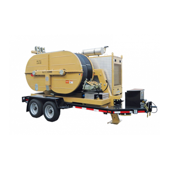
- Page 9 TYPOLOGY AND USING FIELD The puller tensioner mod. PT2450 It is suitable for the traction of 1 or 2 conductors with a diameter of max 42 mm and for the recovery of 1 or 2 rope with max diameter 21.
- Page 10 Electric System 24 V Panels with sound absorbing material for acoustic insulation. MANUAL READING For further analysis of DIESEL ENGINE VOLVO TAD570 installed on the PT2450, read carefully the reference manual. Manual: MI-PT2450-050-00-GB Date: 28.07.2018 Author: AT Page: 7 of 89...
- Page 11 HYDRAULIC PULLER TENSIONER PT2450 GENERAL INFORMATION FOR THE MACHINE USE a. Only employed and qualified operators must use the machine. Qualified operators is intended to be the person who has received a qualified training from the using Company or, as alternative, from the manufacturer.
- Page 12 HYDRAULIC PULLER TENSIONER PT2450 KNOWLEDGE AND CARE OF THE INSTRUCTION MANUAL a. The information contained in the instruction manual applies to all the operators charged with the use and/or the maintenance of the machine. b. The instruction manual is not a training manual.
- Page 13 HYDRAULIC PULLER TENSIONER PT2450 3.11 USE NOT ALLOWED The machine must not be used: a. for lifting persons and/or goods b. in closed/unventilated sites or, however, not sufficiently airy (tunnel or similar) c. in sites with presence of gas that can be easily set on fire or explosives d.
- Page 14 HYDRAULIC PULLER TENSIONER PT2450 3.13 APPLIED NORMS If the machine is commercialized in C.E. responds to the following regulatory framework: 2006/42/CE Norm referring to the laws of the machines. 2014/30/UE Norm referring to the laws of the electromagnetic compatibility. If the machine is commercialized outside the C.E. was made reference to the following regulatory...
- Page 15 HYDRAULIC PULLER TENSIONER PT2450 TRANSPORT AND POSITIONING INSTRUCTIONS MACHINE LIFTING For the machine lifting use only devices as overhead travelling cranes or lift trucks, with a capacity equal to the mass to be lifted. The instruments used for the machine lifting (ropes, cables, hooks, etc.) have to be exactly dimensioned as compared to the mass to be lifted and have to be connected to the proper elements foreseen on the machine.
- Page 16 HYDRAULIC PULLER TENSIONER PT2450 DANGER the non-respect of the above mentioned conditions may cause dangerous situations as well as damages to the machine with the consequent decline of any warranty condition. TRANSPORT TYPOLOGIES AND PACKAGE Transport by land by truck The machine comes without all the liquids that can be set on fire and protected in the most exposed and delicate parts by means of cardboard and/or plywood and/or polyethylene extensible film.
- Page 17 HYDRAULIC PULLER TENSIONER PT2450 TOWING TRANSPORTATION The machine is not arranged to be towed on the road. Possible displacements on trailer in the working site must be carried out by a connection to the towing unit by means of the towing eye on the drawbar (tab. 1) and in the respect of the speed limits of the axle. The used towing unit must be homologated for towing trailers with mass and dimensions as per the described machine.
- Page 18 HYDRAULIC PULLER TENSIONER PT2450 d. anchor the machine to the ground using 2 ropes each having a load of use guaranteed minimum of 3 time the maximum force allow of the machine. linking the connections provided (tab. 2 pos.8 and tav.3 pos.10), in the rear of the machine, with anchoring pegs.
- Page 19 Tesmec S.p.A. is not liable for damage to the vehicle, to persons and property, also against third parties in the event of failed or incorrect observance of even one of the instructions given in this manual, or in general, the lack of enforcement of existing legislation.
- Page 20 HYDRAULIC PULLER TENSIONER PT2450 CONTROL PANEL and RADIO CONTROL The machine is equipped with a control panel on the electric box and a radio remote control to handle the stringing operation. ELECTRIC GPS control receiving Switch on key Control Panel...
- Page 21 HYDRAULIC PULLER TENSIONER PT2450 RADIO REMOTE CONTROL Elettronic Connection switch (if allow) Rope clamp switch Machine Control Joystick Pull-Force Control Reel Winder Syncronizer device Control switch (if allow) Emergency Push-Button Connection Remote control Reel Winder Control (for manual use) Remote control...
- Page 22 HYDRAULIC PULLER TENSIONER PT2450 The radio control display is equipped with 4 control pages of the main parameters of the machine, and the operator cannot remain near the machine during the stringing operation. Alarm Machine Push button menù pages. Working parameter...
- Page 23 HYDRAULIC PULLER TENSIONER PT2450 You can switch from page to page, by using the “control pages button” placed on the radio control. Page to set the pull force value This page allows the operator to set the pull value on the machine.
- Page 24 HYDRAULIC PULLER TENSIONER PT2450 The radio control display is equipped with a bar for signaling an alarm or various machine functions: WORKING MACHINE CONFIGURATION PULLER OR TENSIONER CIRCUIT 1 WORKING MACHINE CONFIGURATION PULLER OR TENSIONER CIRCUIT 2 MACHINE ALARM ALLARMS FROM...
- Page 25 HYDRAULIC PULLER TENSIONER PT2450 Connection the remote control The main control of the machine is on the remote control. The machine is always set to connect the remote control. It will be possible to see the status of the connection, between the state of the icons in the main control panel and on the display control panel.
- Page 26 HYDRAULIC PULLER TENSIONER PT2450 2. Turn On the radio remote control. Rotate the switch to ON position. 3. Push the green button on the radio remote control. Green button to connect on the machine 4. Check the status of the remote control connection on the display machine and on the transmitter.
- Page 27 MANUAL READING For further analysis about AUTEC remote control allow on the PT2450, read carefully the reference manual. The operator also can check the status of connection between the blink of light.
- Page 28 HYDRAULIC PULLER TENSIONER PT2450 5. If the operator need to disconnect the remote control, rotate the switch to OFF position. WARNING When the radio remote control lost the signal, the machine will stop immediately if the machine working like a PULLER.
- Page 29 HYDRAULIC PULLER TENSIONER PT2450 MULTIFUNCTION DISPLAY AND MACHINE PARAMETERS The machine control panel is equipped with a 7 "multifunction touch display. When the power is turned on, the following main working screen opens, which contains all the elements for controlling the machine and monitoring it in real time.
- Page 30 HYDRAULIC PULLER TENSIONER PT2450 5.5.1 WORKING AREA MACHINE In this chapter it will be described the command and graphic representation in the main control panel. Circuito 1 Circuito 2 1- Virtual Dynamometer (circuit 1 and 2): Displays the pull set and the actual shooting on the machine, depending on the choice of configuration work by the operator (between the button n°5).
- Page 31 HYDRAULIC PULLER TENSIONER PT2450 Machine in PULLER configuration Machine in TENSIONER configuration “CIRCUIT 1 + CIRCUIT 2” “CIRCUIT 1 + CIRCUIT 2” Machine in PULLER configuration Machine in TENSIONER configuration “CIRCUIT 1” or “CIRCUIT 2” “CIRCUIT 1” or “CIRCUIT 2”...
- Page 32 HYDRAULIC PULLER TENSIONER PT2450 BLUE ARROW: indicates the CURRENT pull value in KN on the reference scale. RED ARROW: TENSIONER machine: Indicates the pull value SET in KN. PULLER machine: Indicates the LIMIT pull value in KN. At the center of the virtual dynamometer, they show the following symbols, which can have different configurations: MACHINE IN PULLER CONFIGURATION.
- Page 33 HYDRAULIC PULLER TENSIONER PT2450 5- Button to choose “Machine Operating Mode” and “Meter counter reset”: through this button, it will show the menu between the operator can select the scale of the pull to be displayed (MACHINE TENSIONER or MACHINE PULLER). push the button to change the type of scale.
- Page 34 HYDRAULIC PULLER TENSIONER PT2450 6- Circuit Management Button Reel elevator/Reel winder circuit 1 and 2 : through this button, the operator has the option to choose how to use the reel elevators circuit or reel winder. It is possible to choose from: Reel elevator circuit STRINGING mode In this configuration, the reel elevators circuit is pressurized automatically.
- Page 35 HYDRAULIC PULLER TENSIONER PT2450 8- Alarms and warning lights: Radiator Status [Black: Turned off – Red: Problem – Green: Switched on] Engine alarm [Black: Turned off – Yellow: Alarm to engine see dedicated page] Engine alarm [Black: Turned off – Yellow: Alarm to engine...
- Page 36 HYDRAULIC PULLER TENSIONER PT2450 5.5.2 Machine menu On the right side of the main work screen, lists the available machine menu. PULL RECORDER Menu identified with the symbol MACHINE SERVICES Menu identified with the symbol MACHINE SETTING Menu identified with the symbol...
- Page 37 HYDRAULIC PULLER TENSIONER PT2450 5.5.2.1 Pull Recording Menu Between the menù “Pull recording menù” it’s possible to : Betwwen the “REC” button of the relative circuite, it’s possible record the key parameters of the • machine during the stringing operations. It’s possible to print the record simultanelly during the stringing opearation or in a second time with the external printer;...
- Page 38 HYDRAULIC PULLER TENSIONER PT2450 Name constructor or other information. Customer Name operator or other information. Operator Name Project or other information. Project Type cable or other information. Cable type Maximum shooting value beyond which an alarm is displayed during printing Maximun Force Recording interval expressed in meters.
- Page 39 HYDRAULIC PULLER TENSIONER PT2450 “REC” button: The icon of the REC button is displayed in different ways, depending on the machine's working configuration set in the relevant "Machine settings" menu → see menu Machine with “indipendent circuit” (See cap.5.9) →...
- Page 40 HYDRAULIC PULLER TENSIONER PT2450 “ACK” button: Pressing the button “ACK” it’s possible to see the recorded data during the stringing operations: Data storage on only the selected Data storage on USB all recordings made Print Registration Upwards scroll Downwards scroll...
- Page 41 HYDRAULIC PULLER TENSIONER PT2450 5.5.2.2 Machine Services Menu The screen, allows you to scroll through the options available to the machine and allows control through the functions shown in the left column. By the symbol , you can scroll through the available menu.
- Page 42 HYDRAULIC PULLER TENSIONER PT2450 CONTROL FRONT PLUG Submenù “Rope clamp Control”; Rope clamp Rope clamp opening opening Circuit 1 Circuit 2 Rope clamp Rope clamp closing closing Circuit 1 Circuit 2 Sub-menu EXIT CONTROL ROPE CLAMP Manual: MI-PT2450-050-00-GB Date: 28.07.2018...
- Page 43 HYDRAULIC PULLER TENSIONER PT2450 Submenù “Control Rear plug”; Lift Machine Lower Machine CONTROL REAR PLUG Manual: MI-PT2450-050-00-GB Date: 28.07.2018 Author: AT Page: 40 of 89...
- Page 44 HYDRAULIC PULLER TENSIONER PT2450 5.5.2.3 Menù “SETTING MACHINE” From the "Machine settings" menu it is possible to access the following sub-menus by pressing the relative button: “Type of oil and circuit pressure control”; • “General settings of the machine control panel”;...
- Page 45 HYDRAULIC PULLER TENSIONER PT2450 Submenù “General settings of the machine control panel” • Setting data 1- Setting Screen language; 2- Setting Display brightness; 3- Setting the speed of stringing and pull set units of measure; 4- Setting temperature units of measure;...
- Page 46 Icon about the electronic syncronize active Machine working configuration The puller-tensioner PT2450 have the possibility to work in this configuration: a. Machine with independent bull-wheel; b. Machine mechanical and hydraulic connected; c. Machine electronic connected; 1- Button for machine configuration in mode “a” and “b”...
- Page 47 HYDRAULIC PULLER TENSIONER PT2450 2- Button for machine configuration in mode “c” This button allows to activate / deactivate the following working configurations of the machine with the visualization, in the central part of the menu, of the active configuration Machine with Electronic connection.
- Page 48 In case of electronic or hydraulic system malfunction, please contact your service agency Tesmec. The screen described here, can be used by customer service Tesmec, to monitor the status of the inputs and outputs as a result of electronic malfunctions detected.
- Page 49 128 and 256 = Malfunction; In radio operation monitoring screen control, there is another button that lets you access a menu by password. This menu can be used only and exclusively under Tesmec assistance authorization. Manual: MI-PT2450-050-00-GB Date: 28.07.2018...
- Page 50 HYDRAULIC PULLER TENSIONER PT2450 If it detects a malfunction of the controls on the radio control, it is possible to completely exclude the radio control and control the machine from the main screen machine. In the radio control management screen, you can enable or disable the radio control and / or on-screen controls.
- Page 51 HYDRAULIC PULLER TENSIONER PT2450 ATTENTION Disconnect the radio control to anything bull-wheels rotation speed (stopped machine). ATTENTION Taking command from the screen to the radio control, the stringing parameters are not transferred. The machine is reset by taking the parameters set on the radio control.
- Page 52 HYDRAULIC PULLER TENSIONER PT2450 This will make it possible: 1- Control the pressure in the circuit reel elevators; 2- Increase the pressure in the circuit reel elevators circuit 1; 3- Decrease the pressure in the circuit reel elevators circuit 1;...
- Page 53 HYDRAULIC PULLER TENSIONER PT2450 This will make it possible: 1- Control of the recovery/release single circuits (bull-wheels virtual joystick); 2- Release circuit with bull-wheels circuit 1 (bull-wheels virtual joystick); 3- Recover circuit with bull-wheels circuit 1 (bull-wheels virtual joystick); 4- Release circuit with bull-wheels circuit 2 (bull-wheels virtual joystick);...
- Page 54 HYDRAULIC PULLER TENSIONER PT2450 Extraordinary machine maintenance settings • Hour counter Reset (h) Upwards scroll Downwards scroll In this menu it is possible to set the time (in hours) of the alarms of the programmed maintenance alarms of the machine: when the set time is reset, when the control panel is switched on, the maintenance warning will be displayed.
- Page 55 HYDRAULIC PULLER TENSIONER PT2450 5.5.2.5 ALARMS MENU and ALARMS SUB-MENU. If during operations stretching, you display a warning and / or error, you can be able to analyze the status or the cause through the four dedicated screens, which can be accessed through the menu scroll key shown at the bottom right of the screen main work.
- Page 56 HYDRAULIC PULLER TENSIONER PT2450 Engine error description • Engine Alarms Description Upwards scroll Downwards scroll This screen allows you to view the description of the active faults on the engine at that time. Historic Machine Alarm • Salvataggio lista allarmi...
- Page 57 HYDRAULIC PULLER TENSIONER PT2450 Historic Engine Alarm • Historic Engine Alarm Displays a list of errors reported by the diesel engine of the machine. Each error is highlighted by the IMF SPN code and description of the same and, in the right of the column shows the start and end of an error message.
- Page 58 HYDRAULIC PULLER TENSIONER PT2450 MACHINE STARTING ATTENTION: Before starting the work and turn on the diesel engine, check that the key off the battery is inserted and turned to the ON position (Tav.4 pos.1). a. Turn the key consensus starter machine positioned on the panel of the power unit. (tab.8 pos.2) b.
- Page 59 HYDRAULIC PULLER TENSIONER PT2450 f. Through the dedicated button, select the operating mode in which you want to use the machine (PULLER or TENSIONER). This button displays the appropriate scale on the virtual dynamometer, depending on the chosen configuration. Refer to the symbolist specified in chapter 5.5.1.
- Page 60 HYDRAULIC PULLER TENSIONER PT2450 CONNECTION MACHINE - HYDRAULIC HEAD OR REEL WINDER Machine can feed 2 reel elevators with hydraulic head or 2 reel winders made by Tesmec, both functioning as tensioner and puller. Each hydraulic head (or each reel winder) has a connecting kit consisting of two pipes.
- Page 61 HYDRAULIC PULLER TENSIONER PT2450 ROPE OR CONDUCTOR MACHINE CHARGING In the wire and conductor charging phases on the machine, they can be used two special commands, which I allow the operator to separately manage the movement of the bull-wheels or connected to the machine reel elevators.
- Page 62 HYDRAULIC PULLER TENSIONER PT2450 MACHINE USE – INDIPENDENT BULL-WHEEL The machine is fully automatic and is able to independently manage variations of load or speed of stringing, self-adjusting the number of revolutions of the engine, turning on and off of the radiator, the rotation speed of the reel elevators.
- Page 63 HYDRAULIC PULLER TENSIONER PT2450 d. Between the dedicate switch, release the conductor on the bull-wheel opening the rope clamp. Gently move the lever (tab. 9, pos.2 and pos.8) to the position (down), the negative brake will open automatically. The machine is ready for working and automatically start to recover if the pull in the rope is less than that of the puller or will begin to release braking if the kinks in the rope is greater than that of the puller.
- Page 64 HYDRAULIC PULLER TENSIONER PT2450 MACHINE USE – ELECTRONIC CONNECTION WITH INDIPENDENT BULL-WHEEL The electronic connection allow to connect electronically circuit 1 and circuit 2 and the operator have the possibility to control both circuit with the one series of controls.
- Page 65 HYDRAULIC PULLER TENSIONER PT2450 3- When the electronic connection is active, the remote commands will be distributed as follows (with reference to Table 9): RADIO REMOTE CONTROL USE IN ELECTRONIC CONNECTION Circuits control 1 Circuits control 2 Active Inactive Pos.1 e 8 – Recovery / Release...
- Page 66 HYDRAULIC PULLER TENSIONER PT2450 If you are operating through the controls placed on the panel, then without the radio remote control connected to the machine (see chapter 5.5.2.4), the buttons for activating the electronic connection and synchronization will be displayed on the "machine work configuration choice" screen (see chapter 5.5.2.3).
- Page 67 HYDRAULIC PULLER TENSIONER PT2450 MACHINE USE – MECHANICAL CONNECTION BULL-WHEEL In this configuration, the machine hydraulically connects Circuit 1 to Circuit 2 so that the performance of the individual circuits can be combined to reach a maximum tensioning force of 100 KN (50 kN + 50 kN).
- Page 68 HYDRAULIC PULLER TENSIONER PT2450 3- When the hydraulic and mechanical connection is active, the radio control commands will be distributed as follows (with reference to Table 9): RADIO REMOTE CONTROL USE IN MECHANICAL CONNECTION Comandi circuito 1 Comandi Circuito 2...
- Page 69 HYDRAULIC PULLER TENSIONER PT2450 POINTS TO REMEMBER a. The pressure of the feeding circuit (see par.5.5.2.3) must be higher than 25 bar: otherwise, the stationary brakes will be damaged. b. Adjust the pull of the reel elevators with hydraulic head at minimum indispensable value: otherwise, the hydraulic oil will be uselessly heated and dangerous counter pulls may arise.
- Page 70 HYDRAULIC PULLER TENSIONER PT2450 AVAILABLE DEVICES The machine can be equipped with the following additional device: MACHINE ELECTRONIC CONNECTION (ALL.089) This device allows a single operator to control multiple "twin" machines (up to a maximum of 4 machines) simultaneously, synchronizing the stringing operations (as regards the main operating parameters).
- Page 71 HYDRAULIC PULLER TENSIONER PT2450 6.1.1 MACHINES SET-UP Before use, the machines must be set up to be used in connection by assigning the correct identification numbers. When machines are connected, the machine with the highest reference number is the MASTER machine, while the lower number machines are all SLAVE machines.
- Page 72 HYDRAULIC PULLER TENSIONER PT2450 1- Button to choose the number machine; 2- Button to activate the connection (it allowed to pass the commands between machine SLAVE with lower N° to the machine MASTER with higher number); 3- Display of the status check of the single machine (the box of the machine on which it is working is highlighted);...
- Page 73 HYDRAULIC PULLER TENSIONER PT2450 a.5) Repeat the procedure described above on the panel of each machine supplied, you will have the following screen configuration; b) MACHINE electronic connection Once the machine number has been defined on the control panel of each machine it is necessary to connect the machines to each other, following the procedure for a maximum of four machines: b.1) On the panel of the machine N°1 –...
- Page 74 HYDRAULIC PULLER TENSIONER PT2450 b.2) On the panel of the machine N°2 – SLAVE, push the relative button, to connect the nearby in machine N° 3 – SLAVE b.2) b.3) On the panel of the machine N°3 – SLAVE, push the relative button, to connect the nearby in machine N°...
- Page 75 HYDRAULIC PULLER TENSIONER PT2450 The connection icon also appears in all "machine function menus" of SLAVE machines: Icon connected machine Machine menù function With the machines connected to each other, the controls of the SLAVE machines pass to the MASTER machine and can be moved simultaneously, using the radio control of the MASTER machine or, in the case of disconnected or emergency radio control, they can be moved from the control panel, again of the MASTER machine.
- Page 76 HYDRAULIC PULLER TENSIONER PT2450 6.1.2 COMMAND “CONNECTED MACHINE” In the following pages there are the possible commands that can be made with the machines in electronic connection: Joystick speed control synchronize Pull force Reel winder pressure Rope switch value control...
- Page 77 HYDRAULIC PULLER TENSIONER PT2450 Depending on the working configuration of the individual machines (see chapter 5.5.2.3), the following commands can be executed: Switch Electronic connection Manual: MI-PT2450-050-00-GB Date: 28.07.2018 Author: AT Page: 74 of 89...
- Page 78 HYDRAULIC PULLER TENSIONER PT2450 LEGENDA: J = Joystick 1 = Circuit 1 2 = Circuit 2 S = machine SLAVE M = machine MASTER = command activated = command de-activated = with machine in TENSIONER configuration it’s possible to control the “force value”...
- Page 79 HYDRAULIC PULLER TENSIONER PT2450 MACHINE IN MECHANICAL CONNECTION BULL-WHEEL STATUS SWITCH ON STATUS SWITCH ON COMAND CIRCUIT MOVEMENT SLAVE (S) MACHINE MASTER (M) MACHINE 2M+1M+2S+1S In the machine work configuration with "independent circuits" and "dependent circuits" the following commands can be use: Active the synchronizer with the relative switch on the radio remote control on the MASTER machine;...
- Page 80 HYDRAULIC PULLER TENSIONER PT2450 6.1.3 ELECTRONIC SYNCRONIZE The activation of the electronic synchronism allows to automatically equalize the speeds of all the circuits connected to each other with machines in working configuration "PULLER" or "TENSIONER", in order to have the conductors or ropes at the same height, during operations of stringing.
- Page 81 HYDRAULIC PULLER TENSIONER PT2450 Set pull force on Set pull force in SLAVE machine all machine ± XX KN XX KN on MASTER MACHINE Machine in “PULLER” configuration: • With the joystick of the MASTER machine it is possible to set the recovery speed on all machines, while via the joystick of the SLAVE machines, it’s possible to make a small adjustment on the recovery speed of...
- Page 82 HYDRAULIC PULLER TENSIONER PT2450 6.1.4 TEMPORARY DISCONNECTION WITH ELECTRONIC CONNECTION When the machines are electronically connected, the operator can temporarily disconnect one or more machines from the other. This feature is only available when all connected machines are stop and not working (the MASTER machine joystick in the center).
- Page 83 HYDRAULIC PULLER TENSIONER PT2450 6.1.5 CONDITIONS OF ALARM WITH CONNECTED MACHINES The following conditions may occur, on one or more connected machines, which generate an alarm with consequent stoppage of the stringing operations and the stop of the diesel engine of all the machines Pressing the emergency stop on the panel in one of the connected machines;...
- Page 84 HYDRAULIC PULLER TENSIONER PT2450 SAFETY CONDITIONS SAFETY DEVICES Machine has been equipped with the following safety devices: 1. load-limiting device with automatically stop of the engine once the max. pre-set load value has been exceeded 2. mechanical negative safety brake for movement stop in case of lack of hydraulic pressure 3.
- Page 85 HYDRAULIC PULLER TENSIONER PT2450 Each situation of danger or alarm is signaled on the main display screen. In case of alarm situations, also it triggers an emergency acoustic signaling. In case this indication appears, see the alarm list in the dedicated menu...
- Page 86 HYDRAULIC PULLER TENSIONER PT2450 PERIODIC OPERATIONS Daily, before starting the work, the operator has to verify the functionality of the machine safety devices. ATTENTION: do not modify for any reason safety devices of the machine because the manufacturer declines any responsibility as consequence of the non- functioning of the same.
- Page 87 HYDRAULIC PULLER TENSIONER PT2450 MAINTENANCE GENERAL PRESCRIPTIONS ATTENTION: possible repairs not carried out by the manufacturer and not allowed by a written authorization relieve the manufacturer for any responsibility in case of accidents to persons or damages to things and/or to the machine, causing also the loss of warranty.
- Page 88 HYDRAULIC PULLER TENSIONER PT2450 ENDOTHERMIC ENGINE MAINTENANCE For the specific maintenance of the engine, see the enclosed use and maintenance booklet. For filling the fuel, use the filling cap on the tank. For filling the radiator liquid, use the filling cap on the radiator.
- Page 89 HYDRAULIC PULLER TENSIONER PT2450 ATTENTION: make maximum care when filling to make sure no foreign matter, which could cause irreparable damages to the circuit’s components, enters along with the oil. For further maintenance operations of installed mechanic components (reduction gear, negative brakes), refer to the enclosed documentation.
- Page 90 HYDRAULIC PULLER TENSIONER PT2450 8.11 SUMMARY TABLE FOR ORDINARY MAINTENANCE In this card are listed main operation of periodic maintenance and relevant intervals. Interval Part Object Daily 50 h 250 h 500 h 1500 h Engine oil Oil filter Cooling liquid...
- Page 91 HYDRAULIC PULLER TENSIONER PT2450 HOW TO DISABLE THE MACHINE TRANSPORT Before transporting the machine, empty any liquid that can be set on fire contained in the machine (oils and fuels). Transport must be effectuated as per the specifications described in chapter 3 (Transport and positioning instructions).
- Page 92 HYDRAULIC PULLER TENSIONER PT2450 10. ENCLOSED DOCUMENTS 10.1 TABLES 10.2 SYTEMS 10.3 OTHER DOCUMENTS Manual for engine use and maintenance Manual: MI-PT2450-050-00-GB Date: 28.07.2018 Author: AT Page: 89 of 89...
- Page 93 PULLER-TENSIONER MOD. PT2450 TABLES - 24050 Grassobbio (Bg) via Zanica, 17/O - 24060 Endine Gaiano (Bg) via Pertegalli Tel. 0039 / 035 / 4232911 Tel. 0039 / 035 / 825024 Fax 0039 / 035 / 4522445 Fax 0039 / 035 / 826375 E-mail: info@tesmec.it...
- Page 94 HYDRAULIC PULLER‐TENSIONER PT2450 Table 1 – Rope charging Machine with indipendent Bull-wheel (50 KN and 50 KN). Table : MI‐PT2450‐050‐00‐IT Data: 06.08.2018 Autor: AM Page: 1 di 11 ...
- Page 95 HYDRAULIC PULLER‐TENSIONER PT2450 Machine with mechanical and hydraulic connection (100 kN). Table : MI‐PT2450‐050‐00‐IT Data: 06.08.2018 Autor: AM Page: 2 di 11 ...
- Page 96 HYDRAULIC PULLER‐TENSIONER PT2450 Table 2 – Bull-wheels Lateral View 1. Front plough; 2. Roller for reel elevator rope passing; 3. Front wheel; 4. Hydraulic rope clamp; 5. Rear stabilizers; 6. Bull-wheels; 7. Machine lifting point; 8. Anchor machine point; 9. Gasoline tank;...
- Page 97 HYDRAULIC PULLER‐TENSIONER PT2450 Tavola 3 – Power Unit Lateral View 1. Diesel engine 2. Bull-wheels gearbox; 3. Hydraulic oil tank; 4. Control panel; 5. Rear stabilizers; 6. Manual parking brake; 7. Tires; 8. Sound-absorbing cover panel; 9. Anchor machine point; 10. Window for mechanical connection pin of the bull wheel;...
- Page 98 HYDRAULIC PULLER‐TENSIONER PT2450 Table 4 – Diesel engine area Table : MI‐PT2450‐050‐00‐IT Data: 06.08.2018 Autor: AM Page: 5 di 11 ...
- Page 99 HYDRAULIC PULLER‐TENSIONER PT2450 1. Machine battery-removal; 2. 12V Battery; 3. SCR exhaust muffler; 4. Alternator; 5. Air radiator /diesel engine water; 6. Coolant filling cap; 7. Suction pipe; 8. Air filter; 9. Filter; 10. Gasoil filter; 11. Oil filter; 12. Gear pump services;...
- Page 100 HYDRAULIC PULLER‐TENSIONER PT2450 Table 5 – Hydraulic System Area 1. Hydraulic engine – Negative brake – Main circuit gearbox; 2. Hydraulic oil filter; 3. Hydraulic oil load cap; 4. Hydraulic oil level; 5. Hydraulic oil drain faucet. Table : MI‐PT2450‐050‐00‐IT Data: 06.08.2018 Autor: AM Page: 7 di 11 ...
- Page 101 HYDRAULIC PULLER‐TENSIONER PT2450 Table 6 – Hydraulic Gearbox 1. Hydraulic engine; 2. Negative brake; 3. Reduction gear; 4. Shift lever fine stringing; 5. Gearbox oil level; 6. Gearbox oil filling cap; 7. Negative brake oil filling cap; 8. Negative brake oil level.
- Page 102 HYDRAULIC PULLER‐TENSIONER PT2450 Table 7 – External Drum Elevator Connections 1. Hydraulic oil to hydraulic head delivery – circuit 1; 2. Drainage – circuit 1; 3. Hydraulic oil to hydraulic head return – circuit 1; 4. Hydraulic oil to hydraulic head delivery – circuit 2;...
- Page 103 HYDRAULIC PULLER‐TENSIONER PT2450 Table 8 – Machine Control Panel 1. Control panel with 7” touch multifunction display 2. Machine Ignition key; 3. Power button diesel engine; 4. Emergency button; 5. External printer connection; 6. USB input; 7. Radio control battery charger; 8. Radio control receiving 9.
- Page 104 HYDRAULIC PULLER‐TENSIONER PT2450 Table 9 – Machine Radio control Operational stop button; 14. Active/inactive electronic connection; Joystick release/recovery circuit 1; 15. Active/inactive syncronizer; Pull force control circuit 1; 16. Alarm Led/or several reports; Reel winder control pressure circuit 1; 17. Display data;...
- Page 105 PULLER-TENSIONER MOD. PT2450 ENCLOSED DOCUMENTS - 24050 Grassobbio (Bg) via Zanica, 17/O - 24060 Endine Gaiano (Bg) via Pertegalli Tel. 0039 / 035 / 4232911 Tel. 0039 / 035 / 825024 Fax 0039 / 035 / 4522445 Fax 0039 / 035 / 826375 E-mail: info@tesmec.it...
- Page 106 Ce manuel ne décrit pas les procédures de déroulage, ni on a tache de donner instructions à l'Utilisateur sur les méthodes de déroulage. Le contenu de ce manuel prévoit seulement un texte pour l’utilisation, l’entretien et la liste de pièces de rechange et comme TESMEC conseille d’utiliser la machine même. Pour chaque suggestion pour améliorer cette machine, écrire à l’adresse au-dessous.
- Page 107 Comparative table of suggested oils and greases REDUCTION UNIT - COUPLERS GREASING TYPE HYDRAULIC CIRCUIT OIL FOR ENVIROMENTAL CONDITION: REDUCTION UNIT OIL FOR ENVIROMENTAL CONDITION: GREASE FOR EACH AMBIENT ARTIC WINTER SUMMER TROPICAL ARTIC WINTER SUMMER TROPICAL VISCOSITY VG 22 VG 32 VG 46 VG 68...
- Page 109 S01-00167 CUSTOMER : AFB 621 0050 DATE SIGNATURE SHEET DRAFTSMAN 01/03/2018 Locatelli ARCHIVES FILES: VERIFIED \\ TESMEC \ UT \ EGPSchemiElettrici \ S01-00167 TOTAL SHEET \\ TESMEC \ PLOT \ TESATURA \ S01 \ APPROVED REVIEW DATE SIGN LOG. PROD.
- Page 136 X.+24G/ X.0V (2) XPE (1) X.+12G (1) XF (12/13) X.+4 (3) XC (5) XR (4) X.0V (7) XT (4) X.+5 (2) XM (2) X2 (55/57) X1 (1)
- Page 147 ALARM LIST DESCRIPTION ID MACHINE DESCRIPTION ALARM OR WARNING ID520192 Monitor - Engine Motor - Can Comunication Fault ID520193 Monitor - Card S1 - Can Comunication Fault ID520194 Monitor - Card S2 - Can Comunication Fault ID520195 Monitor - Card S3 - Can Comunication Fault ID520196 Monitor - Card S4 - Can Comunication Fault ID520197...
- Page 148 ALARM LIST DESCRIPTION ID520263 Speed synchronism mode can not be activated ID520288 S1 - Eeprom Error ID520289 S1 - Internal Temperature ID520290 S1 - Battery Value ID520291 S1 - Monitor - Can Comunication Fault ID520292 S1 - Engine Motor - Can Comunication Fault ID520293 S1 - Engine Motor - Battery Not In Charge ID520294...
- Page 149 ALARM LIST DESCRIPTION ID520336 Secondary Stand ReelWinder Pull Set Potentiometer Fault ID520337 BW1 Mechanical Coupling On The Machinery Is Not Concordant ID520338 BW1 StringingMode - StandAloneCV In Use ID520339 BW1 Stringing Mode - ReelWinder Pressure Value Not Correct ID520340 BW1 ReelWinder Pull Value Too Low ID520341 BW1 Stringing Mode - ReelWinder Pull Value Not Correct ID520342...
- Page 150 ALARM LIST DESCRIPTION ID520510 BW2 Auxiliary Pull Value Low ID520511 BW2 Pull Pressure Too High For Release ID520512 BW2 Pull Pressure No Reached ID520513 BW2 Release Function Not Permitted ID520514 BW2 Low Tensioner Active: Function Not Permitted ID520515 BW2 Negative Brake Closure Requested ID520516 BW2 Stringing Mode - Auxiliary Pull Value Already In Use ID520517...
- Page 151 ALARM LIST DESCRIPTION ID520620 S1 - Pin 117 BWRotation - Proportional Pull Valve (BW1) ID520621 S1 - Pin 118 BWRotation - Valve Recovery (BW1) ID520622 S1 - Pin 119 BWRotation - Feedback Proportional Pull Valve (BW1) ID520623 S1 - Pin 120 BWRotation - Feedback Proportional Release- Recovery Valve (BW1) ID520624 S1 - Pin 123 Emergency Relay 01 ID520625...
- Page 152 ALARM LIST DESCRIPTION ID520667 S1 - Pin 116 Engine Diesel - Increase Rpm Relay ID520668 S1 - Pin 116 Engine Diesel - Motor On Segnaling Light ID520669 S1 - Pin 124 Engine - Water Temperature ID520670 S1 - Pin 262 Oil Fan Max Pressure Sensor ID520671 S1 - Pin 268 Engine - Speed Sensor ID520672...
- Page 153 ALARM LIST DESCRIPTION ID520734 S2 - Pin 137 Auxiliary Services - Pull Trasducer (BW2) ID520735 S2 - Pin 138 ID520736 S2 - Pin 139 BWRotation - Pull Trasducer (Input Motor) (BW2) ID520737 S2 - Pin 140 ID520738 S2 - Pin 141 Slow Speed Rotation - Valve (BW2) ID520739 S2 - Pin 142 BW Rope Locker - UnLock Valve (BW2) ID520740...
- Page 154 ALARM LIST DESCRIPTION ID520818 S1 - Pin 119 Feedback Proportional Valve Pull BW1 ID520819 S1 - Pin 120 Feedback Proportional Release- Recovery BW1 ID520820 S1 - Pin 123 ID520821 S1 - Pin 124 Engine - Grid Heater ID520822 S1 - Pin 125 Engine Diesel - Start-Stop PushButton ID520823 S1 - Pin 126 Engine - Battery In Charge ID520824...
Need help?
Do you have a question about the PT2450 and is the answer not in the manual?
Questions and answers