
Related Manuals for MASSO G2

Summary of Contents for MASSO G2
- Page 1 MASSO MASSO Documentation MASSO Documentation v5.18 - 08 Apr,2021 www.masso.com.au Page 1 of 477...
- Page 2 MASSO MASSO Documentation How to use this documentation Using QR codes for viewing interactive content and watching instructional videos. v5.18 - 08 Apr,2021 www.masso.com.au Page 2 of 477...
-
Page 3: Table Of Contents
2. Warnings and Cautions ....................11 3. myWorkshop ......................... 12 4. MASSO - FAQ's ......................16 4.1. About MASSO ......................17 4.2. MASSO Touch - Frequently asked questions ..............19 4.3. Purchasing MASSO ....................21 4.4. Machine conversion and Builds .................. - Page 4 ................... 138 6.13. Auto Loading G-code ....................143 6.14. Probing ........................145 7. Quick Start Guides ...................... 148 7.1. Safe work practices when wiring MASSO ..............149 7.2. Setup MASSO Mill ..................... 153 7.3. Setup MASSO Plasma ....................164 7.4. Setup MASSO Lathe ....................
- Page 5 MASSO MASSO Documentation 8.21. G82 – Drilling Canned Cycle With Dwell ..............219 8.22. G83 – Peck Drilling For Deeper Holes ............... 220 8.23. G90 – Set Distance Mode To Absolute ..............221 8.24. G91 – Set Distance Mode To Incremental ..............
- Page 6 MASSO MASSO Documentation 11.1. Mounting and Mechanical Data ................. 270 11.2. E-Stop Wiring ......................272 11.3. Axis Servo/Stepper examples ................... 276 11.3.1. Gecko 203V ......................279 11.3.2. Gecko G340 ....................... 280 11.3.3. Gecko G540 ....................... 281 11.3.4. Teknic - ClearPath ....................
- Page 7 11.28. MASSO G3 Replacing Damaged Optocouplers ............377 11.29. Spindle RPM Encoder .................... 381 11.29.1. Upgrading the Spindle encoder on MASSO G2 ............384 12. Save & Load Settings ....................386 13. Touch Probe ......................389 14. Tool Setter / Touch Plate ..................393 14.1.
- Page 8 MASSO MASSO Documentation 23. Forums & Email Support ..................469 24. Reporting Bugs & Issues ..................470 25. Payment ........................471 26. Shipping & Delivery ....................473 27. Warranty ........................475 28. Returns ........................476 v5.18 - 08 Apr,2021 www.masso.com.au...
-
Page 9: Masso Documentation
MASSO MASSO Documentation 1. MASSO Documentation Welcome to MASSO documentation. You can quickly search for information using the search bar on the top- right. This documentation covers the MASSO G2, MASSO G3 and MASSO G3 Touch controllers. We have prepared the following quick links to help you find the right information for your project. - Page 10 MASSO MASSO Documentation Purchasing v5.18 - 08 Apr,2021 www.masso.com.au Page 10 of 477...
-
Page 11: Warnings And Cautions
MASSO MASSO Documentation 2. Warnings and Cautions WARNING: Indicates circumstances or practices that can lead to personal injury as well as damage to the controller, the machine, or other equipment. CAUTION: Indicates circumstances or practices that can lead to damage to the controller or other equipment. -
Page 12: Myworkshop
MASSO MASSO Documentation 3. myWorkshop Step1 Log into myWorkshop https://myworkshop.masso.com.au Login using your account email address and password. If your initial account registration link has expired please select Request Account Activation Link and a new registration email will be sent. - Page 13 MASSO MASSO Documentation Step 3 Click your Serial Number Click on the Serial number of your MASSO you want to download Step 4 Click Software Downloads Step 5 Select software version Click on the Download Software box of the software version you wish to download.
- Page 14 MASSO MASSO Documentation Step 6 Download Software Click Download to download the latest version Step 6 Email Software To Email the software update Click the Email button next to the software version you wish to download and the Email Software Download Link box will open. The Email address will already be filled in with your registered Email address however you can enter a different address if you wish to have it sent elsewhere.
- Page 15 MASSO MASSO Documentation v5.18 - 08 Apr,2021 www.masso.com.au Page 15 of 477...
-
Page 16: Masso - Faq's
MASSO MASSO Documentation 4. MASSO - FAQ's v5.18 - 08 Apr,2021 www.masso.com.au Page 16 of 477... -
Page 17: About Masso
I have both a Mill and a Lathe, can I use MASSO to run both? Yes, MASSO can be used to run Mill, Lathe or Plasma. When you purchase your MASSO you are given access to all software and can change between software when you power on your MASSO. - Page 18 There is no extra cost for using multiple software's on one MASSO controller. Can I load a DXF file into MASSO No, MASSO is a CNC controller and uses only Gcode. You need to write or use CAM software to create your Gcode Where can I get a post processor for my CAM software? MASSO has links to some CAM software post processors in the documentation.
-
Page 19: Masso Touch - Frequently Asked Questions
MASSO-G2 model is designed to connect to VGA screens with a 15pin VGA connector and can't run LED/LCD screens. NOTE: Even if a small add-on module to connect the VGA connector of the MASSO-G2 controller to the MASSO Touch screen is made available, MASSO-G2 does not have the memory to add MASSO Touch capacitive touch drivers or screen layouts to support full touch features. - Page 20 Both the models will have exact same software features and user interface. MASSO Touch was developed as per client and OEM requests to have an integrated design and also to solve issues with 3rd party touch screen not working.
-
Page 21: Purchasing Masso
I ordered 3 Axis but need 5, can I upgrade? All MASSO units use the same hardware that is capable of running up to 5 axis. You can purchase the axis upgrade at any time and new software will be added to your myWorkshop portal for easy download. -
Page 22: Machine Conversion And Builds
What inputs and outputs you need. You need to evaluate each existing item to see if it conforms to the MASSO standard and replace those items that do not comply. If you are unsure about a specific piece of equipment please consult the manufacturer's documentation. - Page 23 MASSO MASSO Documentation Relay module Homing sensor MPG Pendant Optical encoder for Spindle Estop switch https://www.masso.com.au/product-category/sensors-accessories/ We do not provide other products and you will need to source them from other suppliers which specialize in these components. v5.18 - 08 Apr,2021 www.masso.com.au...
-
Page 24: Motors And Drives
When connecting servos the encoder connects directly to your servo drive which monitors the position and will send an alarm to MASSO in the event of position loss, the drive is then wired to MASSO using STEP/PULSE and DIRECTION signals. There is no need or option to connect the encoder from motors to MASSO. - Page 25 This is outside the field of the CNC controller. Please consult an engineer who specializes in this field of machine design. What motors and drives do you recommend? MASSO does not recommend any specific 3rd party equipment. v5.18 - 08 Apr,2021 www.masso.com.au...
-
Page 26: Plasma
Does MASSO supply an THC to use with MASSO? In the future, we will be adding a MASSO THC to the MASSO range, designed specifically to work with the MASSO CNC controller. At present, there is no scheduled release date. - Page 27 MASSO MASSO Documentation Pendant Please see these pages for additional information. https://docs.masso.com.au/quick-start-guides/setup-masso-plasma https://docs.masso.com.au/wiring-and-setup/plasma-torch-height-control/how-thc-works v5.18 - 08 Apr,2021 www.masso.com.au Page 27 of 477...
-
Page 28: Encoders
Can I use absolute or linear encoders on axis? MASSO does not support the use of absolute or linear encoders to determine the position or home the machine. Homing sensors or switches are required on each axis to home the machine. -
Page 29: Spindles
MASSO provides a 0~10v, CW and CCW signals to control spindle speed (RPM). Two open-collector optical switches for forward (clockwise) and reverse (counter-clockwise) signals. If your VFD conforms to this format then MASSO will work with your spindle. https://docs.masso.com.au/wiring-and-setup/setup-and-calibration/spindle-vfd-examples How do I connect my Spindle? It is not possible to provide wiring diagrams for every VFD or provide advice on how to configure specific VFD’s. -
Page 30: Tool Changers
Will MASSO work with my machine's tool changer? MASSO has built in a range of tool changer logic for both Mills and Lathes. Please have a look at the current list of tool changers available and compare their logic to the logic requirements of yours to see if there is one suitable for your machine https://docs.masso.com.au/wiring-and-setup/tool-changers... -
Page 31: Support
MASSO support portal or email allows for a record of questions and the answers to be available to members of the MASSO support team to follow up on and refer back to at a future date. It also eliminates issues of international time zones and assists with language barriers through the use of translation. - Page 32 How to use your MASSO support ticket Portal https://youtu.be/2NE4DFL4_Ck Using the MASSO Support Portal The video below takes you through setting up the MASSO support portal step by step and demonstrates how to use it. Scan the QR code to watch the MASSO video tutorial on YouTube Click here to view the video v5.18 - 08 Apr,2021...
-
Page 33: Installing Masso
MASSO MASSO Documentation 5. Installing MASSO v5.18 - 08 Apr,2021 www.masso.com.au Page 33 of 477... -
Page 34: Masso Touch
MASSO MASSO Documentation 5.1. MASSO Touch CAUTION: Semiconductor parts inside the unit can be damaged by electrostatic discharge (ESD). When handling, care must be taken so that the devices are not damaged. Damage due to inappropriate handling is not covered by the warranty. - Page 35 MASSO MASSO Documentation Installing the E-Stop button The E-Stop button needs to be installed first, please follow the steps to install the E-Stop button. Press the two clips and pull the backside of the E-Stop button Bend the switch button as shown above.
- Page 36 LCD Cable connector If for any reason the LCD cable has to be removed and installed back, it must be installed in the direction as shown below else the LCD or the MASSO controller might get damaged. v5.18 - 08 Apr,2021 www.masso.com.au...
- Page 37 Powering the MASSO Touch The MASSO Touch power supply connector is located at the top-right corner of the controller as seen in the picture below. MASSO Touch requires a power supply of 24 VDC with a minimum of 1.5 Amps output.
- Page 38 MASSO MASSO Documentation WARNING: The installation of a 1 amp fuse between your Power Supply and MASSO is required to protect against an accidental short circuit of the auxiliary power connectors on MASSO, such an event can damage the controller beyond repair.
- Page 39 MASSO MASSO Documentation CAUTION: Power and Ground terminals provided on the controller are only to be used for very low current signals. Connecting high current loads can damage the controller beyond repair. v5.18 - 08 Apr,2021 www.masso.com.au Page 39 of 477...
-
Page 40: Powering Masso-G3
The MASSO power supply connector is located at the top-right corner of the controller as seen in the picture below. MASSO requires a power supply between 12 and 24 VDC with a minimum of 1.5 Amps output. - Page 41 MASSO MASSO Documentation INFORMATION: There are multiple Power (Red-colored) and Ground (Black-colored) provided on the controller and can be used to easily wire drives, sensors and switches. Some examples: The Power terminals can be used to provide voltage to sensors or switches for machine homing.
-
Page 42: Powering Masso-G2
The MASSO power supply connector is located at the top-right corner of the controller as seen in the picture below. MASSO requires a power supply between 12 and 24 VDC with a minimum of 1.5 Amps output. -
Page 43: Connecting A Screen
MASSO MASSO Documentation 5.4. Connecting a Screen MASSO uses a standard 15 pin female VGA connector (1024 x 768 screen resolution) INFORMATION: If the monitor only supports HDMI input then a simple VGA to HDMI converter can be used. INFORMATION: The display is a 4:3 aspect ratio and will look distorted when displayed as 16:9 on a widescreen monitor. -
Page 44: Connecting Keyboard & Mouse
Standard USB Keyboard & Mouse can be connected to MASSO, both wired and wireless devices are supported. INFORMATION: MASSO G3 has 4 USB ports and MASSO G2 has 2 USB ports. If more USB ports are required then a USB HUB can also be connected. - Page 45 MASSO MASSO Documentation v5.18 - 08 Apr,2021 www.masso.com.au Page 45 of 477...
-
Page 46: Loading Software To Masso-G3
Information: Summary of install and upgrade process Ensure your Flash drive is formatted to Fat32 Create a folder called MASSO on the flash drive and copy the software file emailed to you into this folder. On powering the MASSO, immediately press the F1 key or for MASSO Touch, tap the screen repeatedly until the Masso software load screen appears. -
Page 47: Loading Software To Masso-G2
The software up-gradation process can be easily performed on site by following the instructions below: Scan the QR code to watch the MASSO video tutorial on YouTube Click here to view the video Information: Avoid using unbranded USB Flash drives as these are known to give issues with software install and upgrades Information: It is advisable to make a backup of your settings before upgrading your software. - Page 48 ZIP file. Power off the controller. NOTE: Make sure that there is nothing connected on the PlayStation connector on the MASSO Insert the USB flash drive into the controller's USB flash drive connector and DO NOT connect a USB hub.
-
Page 49: Admin And User Passwords
Scan the QR code to watch the MASSO video tutorial on YouTube Click here to view the video INFORMATION: If want to lock Masso to prevent unauthorized use, Press CTRL + L and you will be prompted to re-enter the User and Admin Passwords. - Page 50 Removing User login To remove the user login leave the New Password and Confirm Password boxes blank and press Ok. When you next start Masso the user password login box will not be presented. Removing Admin Login Password It is not possible to remove the Admin Login.
- Page 51 Resetting Passwords Should you loose or forget your passwords you will need to contact Masso support with your Masso serial number to get a Password reset file for your Masso which will reset both User and Admin password to default.
-
Page 52: Wiring And Calibration
MASSO MASSO Documentation 5.9. Wiring and Calibration Now the axis and spindle drives can be wired to MASSO, followed by calibration. Please use the below links: Axis Servo/Stepper Examples Spindle VFD Examples v5.18 - 08 Apr,2021 www.masso.com.au Page 52 of 477... -
Page 53: Current Software Versions
Mill, Plasma & Lathe v3.49 (Release Date: 29 Jan, 2021) Masso Link Version 2.0 (Release Date: 29 Jan, 2021) Click here to download MASSO Link software INFORMATION: The latest version of your software is available on your myWorkshop portal INFORMATION: For more information on using your myWorkshop portal please see here:... -
Page 54: Machining With Masso
MASSO MASSO Documentation 6. Machining with MASSO v5.18 - 08 Apr,2021 www.masso.com.au Page 54 of 477... -
Page 55: Loading Software To Masso-G3
Summary of install and upgrade process Ensure your Flash drive is formatted to Fat32 Create a folder called MASSO on the flash drive and copy the software file emailed to you into this folder. On powering the MASSO, immediately press the F1 key or for MASSO Touch, tap the screen repeatedly until the Masso software load screen appears. -
Page 56: Loading Software To Masso-G2
The software up-gradation process can be easily performed on site by following the instructions below: Scan the QR code to watch the MASSO video tutorial on YouTube Click here to view the video Information: Avoid using unbranded USB Flash drives as these are known to give issues with software install and upgrades Information: It is advisable to make a backup of your settings before upgrading your software. - Page 57 ZIP file. Power off the controller. NOTE: Make sure that there is nothing connected on the PlayStation connector on the MASSO Insert the USB FLASH drive into the controller's USB flash drive connector and DO NOT connect a USB hub.
-
Page 58: Admin And User Passwords
INFORMATION: When the controller is powerd up, Caps Key is enabled by default, as of v3.49 for G2 and v4.00 for G3 Caps key is not enabled. Scan the QR code to watch the MASSO video tutorial on YouTube Click here to view the video v5.18 - 08 Apr,2021... -
Page 59: Graphical Interface
MASSO MASSO Documentation 6.4. Graphical Interface v5.18 - 08 Apr,2021 www.masso.com.au Page 59 of 477... -
Page 60: Graphical Interface Version 3
MASSO Documentation 6.4.1. Graphical Interface Version 3 This page describes the User interface on MASSO G2 & G3 running Version 3 software The user interface is divided into 6 screens from F1 to F6, the below video explains each screen in detail. - Page 61 MASSO MASSO Documentation F2 Screen This is the Run screen where you run your GCode files and monitor progress. When you enter this screen you will be prompted for the User Password. Default Password is "HTG". The user password can be changed or removed.
- Page 62 F3 Screen This is the Jog Screen. From this screen you can Home and Jog your machine. You can access MASSO probing functions by pressing the probing button on screen. Press the Home Button for 3 seconds to home the machine Jog and using the Axis + &...
- Page 63 MASSO MASSO Documentation F4 Screen Tool Table, work offset screen and Park location. This is where tool data is stored for each tool including it's name, Z offset and Tool Diameter. Work offsets G54 to G59 are stored in the Work offset table. These values are automatically stored when you zero your axis and you can also manually change them if needed.
- Page 64 MASSO MASSO Documentation F5 Screen Masso have built in wizards that will allow you to create basic Gcode files. The wizards are intended for the most basic of jobs and CAM software is recommended. Additional information on the available wizards v5.18 - 08 Apr,2021...
- Page 65 MASSO Documentation F6 Screen This screen is where you will select files from your USB Flash drive and load them into MASSO. Double click the file you wish to load or select the file and press the load key Once the file loaded it will draw the toolpaths onto the screen for you to view.
- Page 66 MASSO MASSO Documentation v5.18 - 08 Apr,2021 www.masso.com.au Page 66 of 477...
-
Page 67: Graphical Interface Version 4
INFORMATION: The interface can be set as either Horizontal or Vertical by selecting the desired option under F1 General Settings. The Vertical interface is primarily designed for MASSO touch though can be used with any G3 with a suitable touchscreen monitor. - Page 68 MASSO MASSO Documentation F2 Screen This is the Run screen where you run your GCode files and monitor progress. When you enter this screen you will be prompted for the User Password. Default Password is "HTG". The user password can be changed or removed.
- Page 69 F3 Screen This is the Jog Screen. From this screen you can Home and Jog your machine. You can access MASSO probing functions by pressing the probing button on screen. Press the Home Button for 3 seconds to home the machine Jog and using the Axis + &...
- Page 70 MASSO MASSO Documentation F4 Screen Tool Table, work offset screen and Park location. This is where tool data is stored for each tool including it's name, Z offset and Tool Diameter. Work offsets G54 to G59 are stored in the Work offset table. These values are automatically stored when you zero your axis and you can also manually change them if needed.
- Page 71 MASSO MASSO Documentation F5 Screen Masso have built in wizards that will allow you to create basic Gcode files. The wizards are intended for the most basic of jobs and CAM software is recommended. Additional information on the available wizards v5.18 - 08 Apr,2021...
- Page 72 MASSO Documentation F6 Screen This screen is where you will select files from your USB Flash drive and load them into MASSO. Double click the file you wish to load or select the file or press the Load key Once the file loaded it will draw the toolpaths onto the screen for you to view.
- Page 73 MASSO MASSO Documentation Vertical Touch Screen Format INFORMATION: The Vertical interface is primarily designed for MASSO touch though can be used with any G3 with a suitable touchscreen monitor. It includes an on screen keyboard which is permanently dispalyed. F1 Screen This screen allows you to configure your Masso settings.
- Page 74 MASSO MASSO Documentation F2 Screen v5.18 - 08 Apr,2021 www.masso.com.au Page 74 of 477...
- Page 75 MASSO MASSO Documentation This is the Run screen where you run your GCode files and monitor progress. When you enter this screen you will be prompted for the User Password. Default Password is "HTG". The user password can be changed or removed.
- Page 76 MASSO MASSO Documentation v5.18 - 08 Apr,2021 www.masso.com.au Page 76 of 477...
- Page 77 F3 Screen This is the Jog Screen. From this screen you can Home and Jog your machine. You can access MASSO probing functions by pressing the probing button on screen. Press the Home Button for 3 seconds to home the machine Jog and using the Axis + &...
- Page 78 MASSO MASSO Documentation v5.18 - 08 Apr,2021 www.masso.com.au Page 78 of 477...
- Page 79 MASSO MASSO Documentation F4 Screen Tool Table, work offset screen and Park location. This is where tool data is stored for each tool including it's name, Z offset and Tool Diameter. Work offsets G54 to G59 are stored in the Work offset table. These values are automatically stored when you zero your axis and you can also manually change them if needed.
- Page 80 MASSO MASSO Documentation v5.18 - 08 Apr,2021 www.masso.com.au Page 80 of 477...
- Page 81 MASSO MASSO Documentation F5 Screen Masso have built in wizards that will allow you to create basic Gcode files. The wizards are intended for the most basic of jobs and CAM software is recommended. Additional information on the available wizards v5.18 - 08 Apr,2021...
- Page 82 MASSO MASSO Documentation v5.18 - 08 Apr,2021 www.masso.com.au Page 82 of 477...
- Page 83 MASSO Documentation F6 Screen This screen is where you will select files from your USB Flash drive and load them into MASSO. Double click the file you wish to load or select the file or press the Load key Once the file loaded it will draw the toolpaths onto the screen for you to view.
- Page 84 MASSO MASSO Documentation v5.18 - 08 Apr,2021 www.masso.com.au Page 84 of 477...
-
Page 85: Controller Alarms
You can set the machine to automatically stop and start when the door is opened or closed. If you have a G2 you must assign an output as a door alarm even if you do not have a door. Setting this to... - Page 86 To clear issue a new probing command with a valid distance ensuring the probe is not already in an active state. Tool Error Alarm This occurs if you try and load a tool not supported by Masso. EG the tool number is greater that 99 0n the G3 or Greater that 31 on the G2 Drive Alarm When a Stepper or Servo drive goes into an alarm condition the Drive can signal Masso which will put the system into Feedhold and stop the spindle.
-
Page 87: Touch Screen Interface
Being a special request feature, the standard version of the MASSO software will only allow 10 screen tap's so that you can evaluate the features and check your screen support with MASSO. A full version will be available for purchase. - Page 88 MASSO MASSO Documentation Kodak Model: KD15V700 15" DELL Model: E157FPTe Medion Model: MD20165 HP Compaq Model: L5009tm Part No. ELO E476049 EYOYO Model: EM15T Planar Model: PXL2430MW Planar Helium Model: PCT2235 Viewsonic Model: TD2421 iiyama Prolite T2253MTS-B1 ZHIXIANDA v5.18 - 08 Apr,2021 www.masso.com.au...
-
Page 89: Keyboard And Key Shortcuts
MASSO MASSO Documentation 6.6. Keyboard and Key Shortcuts NOTE: Most of the functions can now be accessed easily with mouse but will still require some keyboard shortcuts as below: v5.18 - 08 Apr,2021 www.masso.com.au Page 89 of 477... - Page 90 MASSO MASSO Documentation v5.18 - 08 Apr,2021 www.masso.com.au Page 90 of 477...
-
Page 91: Setting Time
MASSO Documentation 6.6.1. Setting Time MASSO has a built in real time clock and to set system time, a special command in the MDI window can be given in this format Time:HH:MM. Please see the below video for full instructions. -
Page 92: Homing The Machine
Once you are ready to home the machine, press CTRL+ALT+HOME key on the keyboard or hold the HOME button in the F3 screen for 3 seconds. You can also assign one of the input on Masso as a Home Button Input and connect a button to it to home the machine. -
Page 93: Rapid/Jog
MASSO MASSO Documentation 6.6.3. Rapid/Jog Press F3 to goto “F3 – Jog/Rapid” screen. For Jogging use Arrow keys and for Rapid movement press and hold the SHIFT key and use Arrow keys. INFORMATION: MPG can also be used in the F1 screen to jog the axis. -
Page 94: Feed Rate Override
MASSO MASSO Documentation 6.6.4. Feed rate Override Feed rate Override Feed rate override function allows the feed rate to be changed during machining. The range is from 20% to 100% of the specified feedrate and the current feedrate percentage is shown on the screen. -
Page 95: Speed Override
MASSO MASSO Documentation 6.6.5. Speed Override Spindle Speed Override Information: This feature is available on the F2 & F3 Screens. Information: Speed override ranges from 10% to 150% of the specified spindle speed. How to use Press the F12 Key on the keyboard Use the + &... -
Page 96: Mdi Command
MDI window can be used to quickly run any gcode commands and the on screen buttons can be used to control outputs or move axis to home position. INFORMATION: In MASSO G3 the up and down arrow key can be used the select and execute commands from history. Last 20 commands are saved in memory. -
Page 97: Creating New G-Code Files
MASSO MASSO Documentation 6.6.7. Creating New G-Code Files Press F2 to goto the F2 - Program & MDI screen Next press CTRL + N to open a new file name window v5.18 - 08 Apr,2021 www.masso.com.au Page 97 of 477... -
Page 98: Editing G-Code
MASSO MASSO Documentation 6.6.8. Editing G-Code INFORMATION: The Gcode edit function is intended to edit small Gcode files. If your Gcode file is larger than 1800 characters it will not open in the edit screen. Press F2 to goto the F2 - Program & MDI screen Next press CTRL + E to open the edit file window v5.18 - 08 Apr,2021... -
Page 99: Resetting Job Counter
MASSO Documentation 6.6.9. Resetting Job Counter MASSO has a built in job counter that increments everytime a gcode file runs. This counter can be used to see number of parts made in large production work. To reset the job counter back to 0: Goto the F2 - Program &... -
Page 100: Loading & Running G-Code
MASSO Documentation 6.7. Loading & Running G-Code MASSO runs gcode files directly from the USB Flash drive. Please see the below video for instructions on how to load and run gcode files. Files with extensions .nc, .cnc, .tap, .wiz, .txt, .eia are displayed in the F6 - Load File screen. -
Page 101: Resuming Program Or Jump To Line
Restarting the gcode file from start is very time and resource consuming. To be able to effectively restart your machining process from where you left, MASSO has a Resuming Program or Jump to Line feature (from software v3.30). - Page 102 Next click Start from line button and MASSO will process the gcode file up to the line number entered by you. When done MASSO will calculate all the machining parameters from the gcode file as below: Calculate the X, Y and Z axis position to resume machining from.
-
Page 103: Wi-Fi Connectivity
With the MASSO Link software, users can easily view the real-time status of your MASSO controller remotely, transfer gcode files to MASSO from your PC, get tool data from MASSO's memory and generate tools list document that can be used with CAM software. - Page 104 MASSO MASSO Documentation v5.18 - 08 Apr,2021 www.masso.com.au Page 104 of 477...
- Page 105 MASSO MASSO Documentation v5.18 - 08 Apr,2021 www.masso.com.au Page 105 of 477...
- Page 106 Creating your own Wi-Fi network If a Wi-Fi network is not available, MASSO can be used to create a Wi-Fi network and a PC can be connected direclty to MASSO via this Wi-Fi network. This feature is called My MASSO Network.
- Page 107 MASSO Link software window. A folder name can be give and all the files sent to MASSO will be saved on the USB pen drive in this folder, else keeping this blank will save the files on the root folder of the USB pen drive.
- Page 108 MASSO MASSO Documentation Connecting to WiFi network INFORMATION: MASSO Wi-Fi module supports 2.4GHz frequency (IEEE 802.11 b/g/n). towards the bottom right of the screen. In the F2 - Program & MDI screen, click the Wi-Fi icon v5.18 - 08 Apr,2021 www.masso.com.au...
- Page 109 Wi-Fi network, the IP address might be changed by the router. As the IP address is required by MASSO Link software, the new IP address needs to be updated on the PC to be able to connect to the MASSO. Using the Fixed IP Address solves this issue.
-
Page 110: Masso Link Software
6.9.1. MASSO Link Software MASSO Link v2.0 Click on the below operating system links of your choice to download MASSO Link software. INFORMATION: MASSO Link V2.0 requires V4.01 and higher on your MASSO G3 or V3.49 and higher on your MASSO G2 MASSO Link v1.6... -
Page 111: Masso Link - Macos Instructions
After downloading the MASSO Link .dmg file, double click to mount the image. Step 2 Once the image has been mounted, drag and extract the MASSO Link software file on the desktop or in a folder. WARNING: Do not run the MASSO Link file without extracting it from the image. - Page 112 Next right the image file and click Eject. At this stage, the dmg file can also be moved to the bin. Step 4 Double click the MASSO Link icon. INFORMATION: If you are using mac with the M1 chip and if Rosetta is not installed on your system then the above message will be displayed.
- Page 113 MASSO MASSO Documentation On the first run, macOS will warn that the developer cannot be verified, click Cancel. INFORMATION: You will need to follow the below steps once to allow MASSO Link to run on your mac. Step 6 Go to the menu and click System Preferences.
- Page 114 MASSO MASSO Documentation Double click and open Security & Privacy. Step 8 You will see the above message, click the Open Anyway button and close the window. Step 9 v5.18 - 08 Apr,2021 www.masso.com.au Page 114 of 477...
- Page 115 MASSO MASSO Documentation Double click the MASSO Link icon, on first use you will see the above message, click the OK button. Step 10 On first use, a settings file MASSO_Settings.dat will be created in the same folder and a message will be displayed.
-
Page 116: Masso Link - Windows Instructions
MASSO MASSO Documentation 6.9.3. MASSO Link - Windows Instructions v5.18 - 08 Apr,2021 www.masso.com.au Page 116 of 477... -
Page 117: Masso Link - Linux Instructions
MASSO MASSO Documentation 6.9.4. MASSO Link - Linux Instructions v5.18 - 08 Apr,2021 www.masso.com.au Page 117 of 477... -
Page 118: Calibrating Tools
MASSO MASSO Documentation 6.10. Calibrating Tools v5.18 - 08 Apr,2021 www.masso.com.au Page 118 of 477... -
Page 119: Lathe Tool Calibration Steps
MASSO MASSO Documentation 6.10.1. Lathe Tool Calibration Steps INFORMATION: On a lathe machine X axis work offsets are not used or available because changing the X offset would result in change of work piece diameter. For setting the X offset to calibrate each tool, please follow the below procedures. - Page 120 MASSO MASSO Documentation Step 3: Go to F3 – Jog/Rapid screen and touch the tool to the front face of the test piece. Step 4: Go to F4-Tools & Work Offset screen and open the tool number you want to calibrate.
- Page 121 MASSO MASSO Documentation Step 5: Give a name to the tool for your reference and click the Zero button. v5.18 - 08 Apr,2021 www.masso.com.au Page 121 of 477...
- Page 122 MASSO MASSO Documentation Step 6: Now go to F3 – Jog/Rapid screen and touch the tool to the side of the test piece. Step 7: Measure the diameter of the test piece and note the value. WARNING: Do not Jog or move the tool away unit the next step has been completed.
- Page 123 MASSO MASSO Documentation v5.18 - 08 Apr,2021 www.masso.com.au Page 123 of 477...
- Page 124 MASSO MASSO Documentation v5.18 - 08 Apr,2021 www.masso.com.au Page 124 of 477...
- Page 125 MASSO MASSO Documentation Step 8: Go back to F4-Tools & Work Offset screen and enter the measured diameter value in Test Piece (Dia) box and click Touch button. CAUTION: Make sure to select the position of the tool depending if its installed on the front or the back side.
- Page 126 MASSO MASSO Documentation Step 10: Click Save button to save and complete tool calibration. v5.18 - 08 Apr,2021 www.masso.com.au Page 126 of 477...
-
Page 127: Mill Tool Calibration Steps
Step 1: Place the tool setter at a predefined position on the machine. Step 2: On MASSO go to F3-JOG screen, next move the tool in position on top of the tool setter and touch the tool till the tool setter shows exactly 0.00. - Page 128 MASSO MASSO Documentation Step 3: On MASSO go to the F4-Tools screen and select the tool number you would like to assign to this tool. Now press the enter key to open the Edit Tool window. Step 4: In the Edit Tool window give a tool name as per your requirement. Next move the click the Zero button to automatically calibrate the tool, MASSO will calculate the tool height and automatically fill the Z Offset value.
- Page 129 MASSO MASSO Documentation Step 5: Once the tool has been calibrated, please go to F3-JOG screen and move tool away from the tool setter. v5.18 - 08 Apr,2021 www.masso.com.au Page 129 of 477...
-
Page 130: Work Offsets
Here is a great video from CNCnutz explaining the entire process Scan the QR code to watch the MASSO video tutorial on YouTube Click here to view the video v5.18 - 08 Apr,2021 www.masso.com.au... -
Page 131: Conversational Programming
MASSO MASSO Documentation 6.12. Conversational Programming v5.18 - 08 Apr,2021 www.masso.com.au Page 131 of 477... -
Page 132: Lathe Conversational Wizards
MASSO MASSO Documentation 6.12.1. Lathe Conversational Wizards MASSO has built in conversational wizards to easily generate gcode programs for basic machining operations by entering basic information. List of wizards available for Lathe Machines: Outer diameter turn wizard Inside turn wizard... - Page 133 MASSO MASSO Documentation Inside turn wizard v5.18 - 08 Apr,2021 www.masso.com.au Page 133 of 477...
- Page 134 MASSO MASSO Documentation Facing wizard v5.18 - 08 Apr,2021 www.masso.com.au Page 134 of 477...
- Page 135 MASSO MASSO Documentation Drilling wizard v5.18 - 08 Apr,2021 www.masso.com.au Page 135 of 477...
- Page 136 MASSO MASSO Documentation Threading wizard v5.18 - 08 Apr,2021 www.masso.com.au Page 136 of 477...
- Page 137 MASSO MASSO Documentation v5.18 - 08 Apr,2021 www.masso.com.au Page 137 of 477...
-
Page 138: Mill Conversational Wizards
MASSO MASSO Documentation 6.12.2. Mill Conversational Wizards MASSO has built in conversational wizards to easily generate gcode programs for basic machining operations by entering basic information. List of wizards available for Milling Machines: Face cut wizard Profile cut wizard Rectangular pocket wizard... - Page 139 MASSO MASSO Documentation Profile cut wizard v5.18 - 08 Apr,2021 www.masso.com.au Page 139 of 477...
- Page 140 MASSO MASSO Documentation Rectangular pocket wizard v5.18 - 08 Apr,2021 www.masso.com.au Page 140 of 477...
- Page 141 MASSO MASSO Documentation Circular pocket wizard v5.18 - 08 Apr,2021 www.masso.com.au Page 141 of 477...
- Page 142 MASSO MASSO Documentation v5.18 - 08 Apr,2021 www.masso.com.au Page 142 of 477...
-
Page 143: Auto Loading G-Code
Tick the Load 'autoload.nc' on power up option and click Save button. Now MASSO will look for a file autoload.nc on the USB Flash drive every time it powers up or if a USB Flash drive is connected. Once the file is found, its automatically loaded and pressing cycle start will start the job. - Page 144 When this input goes HIGH, MASSO will look for a file autoload1.nc on the USB pen drive, once the file is found, its automatically loaded and pressing cycle start will start the job.
-
Page 145: Probing
MASSO MASSO Documentation 6.14. Probing MASSO supports interactive part probing option that allows the user to probe parts and set work offsets. The following probing features are available: Top of part. Sides of part. Corners of part. Auto find center of holes. - Page 146 MASSO MASSO Documentation v5.18 - 08 Apr,2021 www.masso.com.au Page 146 of 477...
- Page 147 MASSO MASSO Documentation Scan the QR code to watch the MASSO video tutorial on YouTube Click here to view the video v5.18 - 08 Apr,2021 www.masso.com.au Page 147 of 477...
-
Page 148: Quick Start Guides
MASSO MASSO Documentation 7. Quick Start Guides v5.18 - 08 Apr,2021 www.masso.com.au Page 148 of 477... -
Page 149: Safe Work Practices When Wiring Masso
The purpose of this document is to provide information on good work practices while setting up and wiring your MASSO. If you are unsure about the wiring of your machine especially mains voltage equipment, please consult a certified service technician. - Page 150 E-Stop has been pressed. An EStop output is provided on MASSO which will allow you to connect a TTL Relay module to disable your drives, spindle and other external equipment. The output is labeled ES on MASSO.
- Page 151 VFD manuals for the correct method of connection. INFORMATION: Up to two of the MASSO relay inputs can be connected to the ES output. If more relay contacts are required use the TTL relay output to drive a relay with multiple contacts.
- Page 152 While the MASSO relay module is rated for 240V 5amp it is recommended that you do not mix low voltage and mains voltages on the same relay module. A better option is to use the MASSO relay output to operate a separate relay or relays located elsewhere within your control cabinet.
-
Page 153: Setup Masso Mill
VFD though you can connect these as you configure each of these components. Power Please note that a 1 amp fuse must be connected in the feed from your Power supply on the MASSO G3. An accidental short circuiting of the auxiliary power terminals built into MASSO will cause damage to the main board if the fuse is not installed. - Page 154 Scan the QR code to watch the MASSO video tutorial on YouTube Click here to view the video Estop Switch An Estop switch is important and MASSO will not work without one. Please ensure you have your Estop connected. EStop Wiring Hint: How the Estop switch is wired will depend on whether you have a pendant or not.
- Page 155 Hint: The biggest mistake new users make is to ignore the maximum and minimum travel setting. If you leave these at 0 your axis will not move as these form part of MASSO soft limit system. Please note that disabling soft limits under general settings only disables them while machining but you are still bound by them when it comes to jogging your axis.
- Page 156 MASSO MASSO Documentation Rotary Axis Setting up a Rotary Axis Jogging Keyboard key shortcuts page To jog your machine you must be in the F3 Jogging screen. Jogging can be done on the F3 screen with either Mouse, Touch screen, Keyboard or Pendant.
- Page 157 Pendant No software configuration is required to make the MASSO MPG pendant work. Simply plug it in and it will work. To make the Estop button on the pendant work you need to wire the Estop in accordance with the Estop Instructions as per the below links.
- Page 158 10mm or 3/8” a homing alarm will indicate. Homing setup instructions Additional resource video Scan the QR code to watch the MASSO video tutorial on YouTube Click here to view the video Hard Limits The homing inputs double as hard limit inputs after the machine has been homed.
- Page 159 CAUTION: Never change a tool after you have homed your machine unless instructed to do so by MASSO. If you must change a tool without MASSO requesting it then do it before homing or home your machine immediately after to get a new reference. Otherwise your next tool change and all the ones that follow will be wrong.
- Page 160 Click here to view the video Probing This document only covers Z height probing though there are many more probing routines built into MASSO. Z height probing can be done with either inside or outside probing screens. Part probing instructions For probing your Z height enter the thickness of your touch off plate into Z Offset.
- Page 161 MASSO MASSO Documentation v5.18 - 08 Apr,2021 www.masso.com.au Page 161 of 477...
- Page 162 MASSO no matter what you do. As tempting as it is to connect everything at once, please do it step at a time and test as you go. Doing this can take a few extra minutes but can save you hours or days of work figuring out what is wrong.
- Page 163 MASSO MASSO Documentation M4 command. v5.18 - 08 Apr,2021 www.masso.com.au Page 163 of 477...
-
Page 164: Setup Masso Plasma
Power Please note that a 1 amp fuse must be connected in the feed from your Power supply on the MASSO G3. The accidental short circuiting of the auxiliary power terminals built into MASSO will cause damage to the main board if the fuse is not installed. - Page 165 Scan the QR code to watch the MASSO video tutorial on YouTube Click here to view the video Estop Switch An Estop switch is important and MASSO will not work without one. Please ensure you have your Estop connected. EStop Wiring Hint: How the Estop switch is wired will depend on whether you have a pendant or not.
- Page 166 Hint: The biggest mistake new users make is to ignore the maximum and minimum travel setting. If you leave these at 0 your axis will not move as these form part of Masso soft limit system. Please note that disabling soft limits under general settings only disables them while machining but you are still bound by them when it comes to jogging your axis.
- Page 167 MASSO MASSO Documentation To jog your machine you must be in the F3 Jogging screen. Jogging can be done on the F3 screen with either Mouse, Touch screen, Keyboard or Pendant. If you cannot Jog use the Mouse to click the jog buttons as users have had issues with faulty Keyboards, pendants and touch screens in the past.
- Page 168 Wiring only one e stop on MPG pendant No software configuration is required to make the MASSO Pendant work. Simply plug it in and it will work. To make the Estop button on the pendant work you need to wire the Estop in accordance with the Estop Instructions.
- Page 169 MASSO MASSO Documentation Scan the QR code to watch the MASSO video tutorial on YouTube Click here to view the video Hard Limits The homing switches double as hard limit switches. To work all hard limit switches must be outside the envelope of axis travel or the hard limit will trip before it reaches the full travel of your axis.
- Page 170 An input can be designated Plasma On / Off and is used to start and stop the Plasma. You can configure any of the MASSO G3 TTL outputs as the Plasma on/off and connect it to your Plasma via the MASSO Relay Module MASSO Relay Module v5.18 - 08 Apr,2021...
- Page 171 The installation of a THC onto your MASSO is covered separately under the section How THC Works This will give you take you through the basic principals of how the THC interfaces with MASSO and explains the Gcode commands specific to the THC functionality The document also shows examples of the 2 methods of connecting your THC to MASSO and explains why one method is preferred over the other.
-
Page 172: Setup Masso Lathe
VFD though you can connect these as you configure each of these components. Power Please note that a 1 amp fuse must be connected in the feed from your Power supply on the MASSO G3. An accidental short circuiting of the auxiliary power terminals built into MASSO will cause damage to the main board if the fuse is not installed. - Page 173 Scan the QR code to watch the MASSO video tutorial on YouTube Click here to view the video Estop Switch An Estop switch is important and MASSO will not work without one. Please ensure you have your Estop connected. EStop Wiring Hint: How the Estop switch is wired will depend on whether you have a pendant or not.
- Page 174 Hint: The biggest mistake new users make is to ignore the maximum and minimum travel setting. If you leave these at 0 your axis will not move as these form part of MASSO soft limit system. Please note that disabling soft limits under general settings only disables them while machining but you are still bound by them when it comes to jogging your axis.
- Page 175 MASSO MASSO Documentation It is important to understand the MASSO Lathe coordinate system and how it works with front and rear tools The coordinate system is fixed no matter whether your tool is front or rear mounted. To assist with setting up your machine the +X, -X, +Z & -Z axis are marked on the screen. X0 is located in the center.
- Page 176 MASSO MASSO Documentation v5.18 - 08 Apr,2021 www.masso.com.au Page 176 of 477...
- Page 177 MASSO MASSO Documentation Jogging Keyboard key shortcuts page To jog your machine you must be in the F3 Jogging screen. Jogging can be done on the F3 screen with either Mouse, Touch screen, Keyboard or Pendant. If you cannot Jog use the Mouse to click the jog buttons as users have had issues with faulty Keyboards, pendants and touch screens in the past.
- Page 178 MASSO Documentation No software configuration is required to make the MASSO MPG pendant work. Simply plug it in and it will work. To make the Estop button on the pendant work you need to wire the Estop in accordance with the Estop Instructions as per the below links.
- Page 179 Set up incorrectly it will restrict machine travel and in extreme cases prevent the machine from moving at all. Minimum and maximum travel setup instructions Additional resource video Scan the QR code to watch the MASSO video tutorial on YouTube Click here to view the video Spindle v5.18 - 08 Apr,2021 www.masso.com.au...
- Page 180 MASSO MASSO Documentation Spindle uses 0-10 volt signal to control speed normally via a VFD. If your spindle does not have speed control you can still do threading as the spindle encoder will track spindle speed for the threading operation however constant surface speed will not function as this requires active speed control.
-
Page 181: Setup Rotary Axis
MASSO MASSO Documentation 7.5. Setup Rotary Axis There are 2 types of rotary axis used on a CNC machine. The Maximum and minimum travel settings will change depending on which type or rotary axis you are setting up. The first and most common is a 4th axis traditionally use on a Mill. This is usually the A axis and it rotates the stock in one axis only while the Z axis moves along it's length in the manner of a lathe. - Page 182 MASSO MASSO Documentation 5 Axis Rotary axis settings are angular and not linear. There is no advantage to using huge step rates with large gear ratios. Breaking one rotation into a million steps will not help accuracy and give you a rotary axis that is slow.
- Page 183 MASSO MASSO Documentation INFORMATION: MASSO has a rotary axis unwind built into the G28 command. G28-return-to- machine-home My Rotary Axis moves Slow This is caused by confusing linear and rotary speeds. Your axis will move at the rate of the slowest axis and reasonable linear speeds can be very slow when changed to degrees per minute and in the worse case scenario can make the machine look like they are not moving at all.
- Page 184 INFORMATION: If you do not wish to install one then set the rotary axis to Home in the Homing settings and MASSO will zero out the machine coordinates for the Rotary axis when you home the machine. This is a common setup for a rotary 4th axis.
-
Page 185: Homing Sensor Identify & Connect
Use a continuity tester to identify if your switches are normally open or closed and wire accordingly. Always used normally closed if you have the option of additional safety. HINT: All MASSO inputs are optically isolated and require a voltage of 5V to 24V from your sensor to register an input. - Page 186 MASSO MASSO Documentation record the results in the table below. If the voltage is greater than 5 volts record a 1 otherwise record a 0. Ignore the polarity shown on the meter. Step 3: Trigger the sensor and measure the voltage between the output & +ve and the output &-ve record the results in the table below.
- Page 187 MASSO MASSO Documentation Type 2 Note: Invert MASSO input for Type 2 sensor v5.18 - 08 Apr,2021 www.masso.com.au Page 187 of 477...
- Page 188 MASSO MASSO Documentation Type 3 v5.18 - 08 Apr,2021 www.masso.com.au Page 188 of 477...
- Page 189 MASSO MASSO Documentation Type 4 v5.18 - 08 Apr,2021 www.masso.com.au Page 189 of 477...
- Page 190 Should a homing switch wire break, the homing input will go high making MASSO think the Homing switch is already active so will attempt to back off the switch and will stop after 10mm.
- Page 191 MASSO MASSO Documentation Additional Resourses For additional information on Homing and how to set it up please see our documentation on setting up homing. v5.18 - 08 Apr,2021 www.masso.com.au Page 191 of 477...
- Page 192 MASSO MASSO Documentation Setting up Homing Detailed video on setting up Homing settings in MASSO Scan the QR code to watch the MASSO video tutorial on YouTube Click here to view the video v5.18 - 08 Apr,2021 www.masso.com.au Page 192 of 477...
-
Page 193: Supported G-Codes
MASSO MASSO Documentation 8. Supported G-codes v5.18 - 08 Apr,2021 www.masso.com.au Page 193 of 477... -
Page 194: G00 - Rapid Motion
MASSO MASSO Documentation 8.1. G00 - Rapid Motion This command is used to move one or more axis at the maximum feedrate to a specified location. If multiple axis are called they will all move together to the desired location in a straight line and arrive at the same time. -
Page 195: G01 - Linear Interpolation Motion
MASSO MASSO Documentation 8.2. G01 - Linear Interpolation Motion This command is used to move one or more axis at the specified feedrate to a specified location. If multiple axis are called they will all move together to the desired location in a straight line and arrive at the same time. -
Page 196: G02 - Circular Interpolation (Clockwise)
I, J values as an offset of the current position or R for radius. The X & Y values define the finish point. Masso uses Incremental I & J values for Arcs Syntax & Parameters G02 starts an arc movement beginning at the X &... - Page 197 MASSO MASSO Documentation v5.18 - 08 Apr,2021 www.masso.com.au Page 197 of 477...
-
Page 198: G03 - Circular Interpolation (Counter Clockwise)
I, J values as an offset of the current position or R for radius. The X & Y values define the finish point. Masso uses Incremental I & J values for Arcs Syntax & Parameters G03 starts an arc movement beginning at the X &... - Page 199 MASSO MASSO Documentation Example program for making an Spiral N10 G00 X20 Y10 Z0 N20 G03 X50 Y40 Z-0.5 I0 J30 In the above example in the first line moves to position X20 Y10 Z0 An arc is made starting at position X20 Y10 and ending at coordinate X50 Y40 with center at position X20 Y40 moving in a counter clockwise direction.
- Page 200 MASSO MASSO Documentation v5.18 - 08 Apr,2021 www.masso.com.au Page 200 of 477...
-
Page 201: G04 - Dwell
MASSO MASSO Documentation 8.5. G04 – Dwell This command is used to Dwell (pause) the execution of the next CNC program block by the specified time. A program dwell time can be created at any point within a program. Syntax & Parameters P Value - The P value is required with G04 and it defines the time to dwell/pause. -
Page 202: G10 - Set Work Offset Values
MASSO MASSO Documentation 8.6. G10 – Set Work Offset Values This command is used to set work offsets values to different offset locations. Syntax & Parameters L2 Value - Must be issued with G10. P Value - The P value is required with G10 and it define the work offset number to change between G54 and G59. -
Page 203: G17 - Xy Plane Selection
MASSO MASSO Documentation 8.7. G17 – XY Plane Selection This command is used to set current work plane to XY. This is the default work plane on power up. Syntax & Parameters Example program N10 G17 The above gcode will set the system to XY work plane. -
Page 204: G18 - Zx Plane Selection
MASSO MASSO Documentation 8.8. G18 – ZX Plane Selection This command is used to set current work plane to ZX. Syntax & Parameters Example program N10 G18 The above gcode will set the system to ZX work plane. v5.18 - 08 Apr,2021 www.masso.com.au... -
Page 205: G19 - Yz Plane Selection
MASSO MASSO Documentation 8.9. G19 – YZ Plane Selection This command is used to set current work plane to YZ. Syntax & Parameters Example program N10 G18 The above gcode will set the system to YZ work plane. v5.18 - 08 Apr,2021 www.masso.com.au... -
Page 206: G20 - Set Machine Units To Inches
MASSO MASSO Documentation 8.10. G20 – Set Machine Units To Inches This command is used to set machine units to Inches. All gcode values after this command will be processed as inches. Syntax & Parameters Example program N10 G20 The above gcode will set the machine units to Inches. -
Page 207: G21 - Set Machine Units To Millimetres
MASSO MASSO Documentation 8.11. G21 – Set Machine Units To Millimetres This command is used to set machine units to Millimetres. All gcode values after this command will be processed as Millimetres. Syntax & Parameters Example program N10 G21 The above gcode will set the machine units to Millimetres. -
Page 208: G28 - Return To Machine Home
MASSO MASSO Documentation 8.12. G28 – Return To Machine Home CAUTION: This command can be used in different combinations and wrong command can result in unexpected rapid motion. Depending if the machine is in Absolute or Incremental mode the behaviour of G28 command will be very different, extra caution should be used when using this command. - Page 209 MASSO MASSO Documentation G00 A900 #Rapids the A axis to A900 (2.5 turns) #Change to Incremental mode G28 A0 #Moves Axis by 0 degrees then moves to A0 wit hin one rotation #Return to Absolute mode In the above example if you specify another coordinate eg: G28 A360 it will move an additional 360 degrees taking the axis to A1260 (3.5 turns) then move to A0 in less than 1 rotation.
-
Page 210: G30 - Move To Parking Position
MASSO MASSO Documentation 8.13. G30 - Move to Parking Position CAUTION: This command can be used in different combinations and wrong command can result in unexpected rapid motion. Depending if the machine is in Absolute or Incremental mode the behavior of G30 command will be very different, extra caution should be used when using this command. - Page 211 MASSO MASSO Documentation Parking Commands CTRL + ALT + P Click the Go to Parking Position button in the MDI Screen Go to Parking Position Button Go to Parking Position Button Configure an input as a Go to Parking Position Input Hold the button for 1 second to activate the feature.
-
Page 212: G32 - Threading Cycle
MASSO MASSO Documentation 8.14. G32 – Threading Cycle This command is used on Lathe machines for running threading cycle synchronised with the spindle. INFORMATION: Taper threading is not supported. Syntax & Parameters Z Value (required) - specifies the end location of the Z axis for threading. The distance value will be the current machine units in use. -
Page 213: G38.2 - Straight Probe Cycle
MASSO MASSO Documentation 8.15. G38.2 – Straight Probe Cycle This command is used for probing parts or fixtures. The axis specified in the G38.2 command will move until the probe touches, if the probe does not touch within the specified distance then the program stops and an alarm is displayed on the screen. -
Page 214: G53 - Move In Absolute Machine Coordinates
MASSO MASSO Documentation 8.16. G53 – Move In Absolute Machine Coordinates This command is used move one or more axis to a specified location. If multiple axis are called they will all move together to the desired location in a straight line and arrive at the same time. The axis can be linear, angular or a combination of both. -
Page 215: G54 To G59 - Select Work Offset Coordinate System
MASSO MASSO Documentation 8.17. G54 to G59 – Select Work Offset Coordinate System The G54 to G59 commands are used to select the current work offset for use. The user can use the F4 screen or G10 command to set the offset values. -
Page 216: G73 - High Speed Peck Drilling
MASSO MASSO Documentation 8.18. G73 – High Speed Peck Drilling This command is Canned Cycle used for high speed peck drilling. Syntax & Parameters G73 followed by axis, R, Q, K & F values. X, Y, Z, A, B Value - specifies the axis you wish to move following the distance to move. The distance value will be the current machine units in use. -
Page 217: G80 - Cancel Modal Motion
MASSO MASSO Documentation 8.19. G80 – Cancel Modal Motion This command is used to cancel Canned Cycles such as G73, G81, G82 & G83. Syntax & Parameters Example program N10 G99 G73 X10 Y10 Z-8 R2 Q1 F100 N20 X20 N30 G80 The first line moves the X &... -
Page 218: G81 - Drilling Cycle
MASSO MASSO Documentation 8.20. G81 – Drilling Cycle This command is Canned Cycle used for drilling cycle. Syntax & Parameters G81 followed by axis, R & F value. X, Y, Z, A, B Value - specifies the axis you wish to move following the distance to move. The distance value will be the current machine units in use. -
Page 219: G82 - Drilling Canned Cycle With Dwell
MASSO MASSO Documentation 8.21. G82 – Drilling Canned Cycle With Dwell This command is Canned Cycle used for drilling cycle with dwell (pause) at the bottom of hole. Syntax & Parameters G82 followed by axis, R, P & F values. -
Page 220: G83 - Peck Drilling For Deeper Holes
MASSO MASSO Documentation 8.22. G83 – Peck Drilling For Deeper Holes This command is Canned Cycle used for peck drilling deeper holes. Syntax & Parameters G83 followed by R, Q, K & F values. X, Y, Z, A, B Value - specifies the axis you wish to move following the distance to move. The distance value will be the current machine units in use. -
Page 221: G90 - Set Distance Mode To Absolute
MASSO MASSO Documentation 8.23. G90 – Set Distance Mode To Absolute This command is used to set mode to absolute. This is the default mode on power up. Syntax & Parameters Example program N10 G90 The above gcode will set the machine units to absolute. -
Page 222: G91 - Set Distance Mode To Incremental
MASSO MASSO Documentation 8.24. G91 – Set Distance Mode To Incremental This command is used to set mode to incremental. Syntax & Parameters Example program N10 G91 The above gcode will set the machine units to incremental. v5.18 - 08 Apr,2021 www.masso.com.au... -
Page 223: G92 - Temporary Work Offset
MASSO MASSO Documentation 8.25. G92 – Temporary Work Offset This command is used set temporary work offset values. The temporary work offsets are used in combination to the main work offsets G54 to G59. Syntax & Parameters G92 followed by axis values. -
Page 224: G92.1 - Cancel Temporary Work Offset
MASSO MASSO Documentation 8.26. G92.1 – Cancel Temporary Work Offset This command is used cancel the G92 temporary work offset values. Syntax & Parameters G92.1 Example program N10 G92.1 The above program cancels the temporary work offset values. v5.18 - 08 Apr,2021 www.masso.com.au... -
Page 225: G93 - Inverse Time Mode
MASSO MASSO Documentation 8.27. G93 – Inverse Time Mode This command is used set the current feed rate mode to Inverse Time Mode. Syntax & Parameters X, Y, Z, A & B These are the destination coordinates of the axis. -
Page 226: G94 - Units Per Minute Mode
MASSO MASSO Documentation 8.28. G94 – Units Per Minute Mode This command is used set the current feed rate mode to Units per Minute Mode. When in this mode the feedrate F value is in units per minute. Syntax & Parameters... -
Page 227: G95 - Feed Per Revolution
MASSO MASSO Documentation 8.29. G95 - Feed Per Revolution This command is used set the current feed rate mode to Feed Per Revolution Mode. When in this mode the feedrate F value is calculated using the current spindle RPM set by user. -
Page 228: G96 - Turn On Constant Surface Speed (Css)
MASSO MASSO Documentation 8.30. G96 – Turn on Constant Surface Speed (CSS) This command is used to enable Constant Surface Speed (CSS) mode in lathe version. Syntax & Parameters G96 followed by D & S values. D Value - This is to set the maximum spindle RPM that the spindle can achieve in CSS mode as the tool gets closer to the center. -
Page 229: G97 - Turn Off Constant Surface Speed (Css)
MASSO MASSO Documentation 8.31. G97 – Turn off Constant Surface Speed (CSS) This command is used to disable Constant Surface Speed (CSS) mode and set to RPM mode in lathe version. Syntax & Parameters Example program N10 G97 In the above example CSS mode is disabled and the system is set back to RPM mode. -
Page 230: G98 - Canned Cycle - Retract Back To The Initial Z
MASSO MASSO Documentation 8.32. G98 – Canned Cycle – Retract Back To The Initial Z This command is used in combination with canned cycles to retract Z axis to the position before canned cycles was started. Syntax & Parameters Example program... -
Page 231: G99 - Canned Cycle - Retract Back To R Plane
MASSO MASSO Documentation 8.33. G99 – Canned Cycle – Retract Back To R Plane This command is used in combination with canned cycles to retract the Z axis to the R plane value. Syntax & Parameters Example program N10 G99 G73 X10 Y10 Z-8 R2 Q1 F100 In the above program, after finishing the drilling cycle the Z axis will retract to the value defined by the R word. -
Page 232: Msg - Print Message To Screen
8.34. MSG - Print message to screen INFORMATION: This gcode is available only on MASSO G3 in version 4.02 or later This command allows the user to add messages to their Gcode which will be displayed on the screen in the tool path area. - Page 233 The video clip below shows an example of using the MASSO MSG gcode to create a backlash test sequence with instructions for the tester to carry out at each step of the process.
- Page 234 MASSO MASSO Documentation Scan the QR code to watch the MASSO video tutorial on YouTube Click here to view the video v5.18 - 08 Apr,2021 www.masso.com.au Page 234 of 477...
-
Page 235: Supported M-Codes
MASSO MASSO Documentation 9. Supported M-codes v5.18 - 08 Apr,2021 www.masso.com.au Page 235 of 477... -
Page 236: M00 - Program Stop
MASSO MASSO Documentation 9.1. M00 – Program Stop This command stops the program. Pressing cycle start will resume the program. Syntax & Parameters Example program N10 G00 X0 Y0 N20 G00 X10 N30 M00 N40 G00 Y10 The first line will move both X and Y axis to 0.00 position. -
Page 237: M01 - Optional Program Stop
MASSO MASSO Documentation 9.2. M01 – Optional Program Stop This command stops the program if optional stop is turned on. Pressing cycle start will resume the program. You can press CTRL + O when on the F2-Program & MDI screen page to toggle between Optional Stop ON/OFF and the status is displayed on the bottom status bar. -
Page 238: M02 - Program End
MASSO MASSO Documentation 9.3. M02 – Program End This command ends the program. Syntax & Parameters Example program N10 G00 X0 Y0 N20 G00 X10 N30 M02 N40 G00 Y10 The first line will move both X and Y axis to 0.00 position. -
Page 239: M03 - Spindle On (Clockwise)
MASSO MASSO Documentation 9.4. M03 – Spindle ON (Clockwise) This command starts the spindle in clockwise direction at the RPM set by the S command Syntax & Parameters M03 - Clockwise command followed with or without S value. S - The S value defines the required RPM. If the S value is not given then the last S value is automatically used. -
Page 240: M03 - Plasma Torch On
MASSO MASSO Documentation 9.5. M03 – Plasma Torch ON In plasma version this command switches On the plasma torch. Syntax & Parameters Example program N10 M03 In this example the plasma torch is switched On. v5.18 - 08 Apr,2021 www.masso.com.au... -
Page 241: M04 - Spindle On (Counter Clockwise)
MASSO MASSO Documentation 9.6. M04 – Spindle ON (Counter Clockwise) This command starts the spindle in counter clockwise direction at the RPM set by the S command Syntax & Parameters M04 - Clockwise command followed with or without S value. -
Page 242: M05 - Spindle Off
MASSO MASSO Documentation 9.7. M05 – Spindle OFF This command stops the spindle. Syntax & Parameters Example program N10 M05 In this example the spindle will be stopped. v5.18 - 08 Apr,2021 www.masso.com.au Page 242 of 477... -
Page 243: M05 - Plasma Torch Off
MASSO MASSO Documentation 9.8. M05 – Plasma Torch OFF In plasma version this command switches Off the plasma torch. Syntax & Parameters Example program N10 M05 In this example the plasma torch is switched Off. v5.18 - 08 Apr,2021 www.masso.com.au... -
Page 244: M06 - Tool Change
T Value – specifies the tool number to change, this value can be used before M06 or after M06 but will have a very different process of tool loading. Scan the QR code to watch the MASSO video tutorial on YouTube Click here to view the video... - Page 245 MASSO MASSO Documentation 5 and M06 is used to tell the system to load the tool. v5.18 - 08 Apr,2021 www.masso.com.au Page 245 of 477...
-
Page 246: M07 - Turn Mist Coolant On
MASSO MASSO Documentation 9.10. M07 – Turn Mist Coolant On This command turns On the Mist Coolant output. Syntax & Parameters Example program N10 M07 In this example the Mist Coolant is turned On. v5.18 - 08 Apr,2021 www.masso.com.au Page 246 of 477... -
Page 247: M08 - Turn Flood Coolant On
MASSO MASSO Documentation 9.11. M08 – Turn Flood Coolant On This command turns On the Flood Coolant output. Syntax & Parameters Example program N10 M08 In this example the Flood Coolant is turned On. v5.18 - 08 Apr,2021 www.masso.com.au Page 247 of 477... -
Page 248: M09 - To Turn All Coolant Off
MASSO MASSO Documentation 9.12. M09 – To Turn All Coolant Off This command turns Off both Mist Coolant and Flood Coolant output. Syntax & Parameters Example program N10 M09 In this example if any of the Mist Coolant or Flood Coolant was On then this code swithces them Off. -
Page 249: M10 - Chuck Or Rotary Table Clamp On
MASSO MASSO Documentation 9.13. M10 – Chuck Or Rotary Table Clamp On This command turns On the Chuck Clamp output. CAUTION: For safety, output LOW means the clamp is On and an interlock signal from the spindle drive must be wired for safety so that the clamp does not open while the spindle/chuck is spinning. -
Page 250: M11 - Chuck Or Rotary Table Clamp Off
MASSO MASSO Documentation 9.14. M11 – Chuck Or Rotary Table Clamp Off This command turns Off the Chuck Clamp output. CAUTION: For safety this output HIGH means the clamp is Off and an interlock signal from the spindle drive must be wired for safety so that the clamp does not open while the chuck is spinning. -
Page 251: M30 - End The Program And Rewind
MASSO MASSO Documentation 9.15. M30 – End The Program And Rewind This command ends the program and moves back to the first line of the gcode file. Syntax & Parameters L Value When added to the M30 command causes the program to be repeated for the specified number of cycles. -
Page 252: M62 - Turn On Digital Output Synchronized With Motion
M62 command has been changed. INFORMATION: MASSO G2 does not support M62 command from version 3.47, please use M64. This command is used to switched ON any of the 16 auxiliary outputs synchronized with the start of the next motion command. -
Page 253: M63 - Turn Off Digital Output Synchronized With Motion
M63 command has been changed. INFORMATION: MASSO G2 does not support M63 command from version 3.47, please use M65. This command is used to switched OFF any of the 16 auxiliary outputs synchronized with the start of the next motion command. -
Page 254: M64 - Turn On Digital Output Immediately
MASSO MASSO Documentation 9.18. M64 – Turn On Digital Output Immediately This command is used to switched ON any of the 16 auxiliary outputs. If this command is used between motion commands then the motion will come to full stop before switching ON the output. -
Page 255: M65 - Turn Off Digital Output Immediately
MASSO MASSO Documentation 9.19. M65 – Turn Off Digital Output Immediately This command is used to switched OFF any of the 16 auxiliary outputs. If this command is used between motion commands then the motion will come to full stop before switching OFF the output. -
Page 256: M666 - Plasma - Turn Thc Function Off
MASSO MASSO Documentation 9.20. M666 – Plasma – Turn THC Function Off This command is used to switched OFF the THC automatic Z axis control function in the plasma version. Syntax & Parameters M666 Example program N10 M666 The above program switches Off the THC function. -
Page 257: M667 - Plasma - Turn Thc Function On
MASSO MASSO Documentation 9.21. M667 – Plasma – Turn THC Function On This command is used to switched On the THC automatic Z axis control function in the plasma version. Syntax & Parameters M667 F Value (optional) - this is the feedrate of the Z axis that the will be used to move torch up/down when in THC mode. -
Page 258: M98 & M99 - Sub Program Call
When a sub program is called, MASSO looks for a separate ".nc" file and runs that as a sub-program. Having a separate file approach means that programs that have common features can now be used used with other programs. - Page 259 NOTE: If the 10.nc file is not found an error message on the screen is displayed and program goes into feedhold. When a program is loaded from F6 screen, MASSO checks that all sub-program files are on the USB and if a file is missing an error is shown to the user M99 End Sub-Program or Return M99 command is used to End Sub-Program or Return back to the main program.
-
Page 260: Cam Post Processors
MASSO MASSO Documentation 10. CAM Post Processors v5.18 - 08 Apr,2021 www.masso.com.au Page 260 of 477... -
Page 261: Plasma Post Processor Requirements
M3 command. Important information Torch touch to trigger switch offset distance is managed by MASSO and is setup during machine calibration, there is no need to set this value in CAM or POST. The touch feedrate and machine maximum Z travel during touch to find the top of the material might be defined in CAM or POST. - Page 262 MASSO MASSO Documentation G38.2 Z-120 F200 G92 Z0 v5.18 - 08 Apr,2021 www.masso.com.au Page 262 of 477...
-
Page 263: Artcam
MASSO MASSO Documentation 10.2. Artcam MASSO Post Processors for Artcam Artcam 2010 CLICK HERE to download (Released: 1/11/2019) Artcam 2015 - 2018 CLICK HERE to download (Released: 1/11/2019) v5.18 - 08 Apr,2021 www.masso.com.au Page 263 of 477... -
Page 264: Bobcad-Cam
CLICK HERE to downloaded the latest Post Processor for Mill and Plasma direct from the Bobcam site. Users will need a support account for the website. Masso posts can be found under Mill_Router and under Plasma. MASSO Post Processor for Lathe... - Page 265 MASSO MASSO Documentation v5.18 - 08 Apr,2021 www.masso.com.au Page 265 of 477...
-
Page 266: Fusion 360
MASSO MASSO Documentation 10.4. Fusion 360 Autodesk POST Processor For Mill. Plasma and Lathe Autodesk Mill, Plasma & Lathe Post Processors Direct download from Autodesk website: Goto Autodesk MASSO page v5.18 - 08 Apr,2021 www.masso.com.au Page 266 of 477... -
Page 267: Sheetcam
MASSO MASSO Documentation 10.5. SheetCAM Tangential Knife POST Processor CLICK HERE to download the POST version 1.0 (14/02/2018) processor file Waterjet POST Processor CLICK HERE to download the POST version 0.1 (11/09/2018) processor file with M62 P1 / M63 P1 turn the... -
Page 268: Vectric Vcarve And Vectric Aspire
(Released: 01/11/2019) Post Processors for Vectric PhotoVCarve CLICK HERE to download (Released: 01/11/2019) Scan the QR code to watch the MASSO video tutorial on YouTube Click here to view the video v5.18 - 08 Apr,2021 www.masso.com.au Page 268 of 477... -
Page 269: Setup And Calibration
MASSO MASSO Documentation 11. Setup and Calibration v5.18 - 08 Apr,2021 www.masso.com.au Page 269 of 477... -
Page 270: Mounting And Mechanical Data
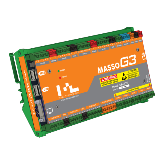
MASSO MASSO Documentation 11.1. Mounting and Mechanical Data MASSO G3 Touch v5.18 - 08 Apr,2021 www.masso.com.au Page 270 of 477... - Page 271 MASSO MASSO Documentation MASSO G3 v5.18 - 08 Apr,2021 www.masso.com.au Page 271 of 477...
-
Page 272: E-Stop Wiring
WARNING: To avoid damage to equipment or hazard to personnel, the system installer should wire the E-Stop button so that pressing the E-Stop button disables all drives and actuators on the machine. The E-Stop relay output on the MASSO should be wired to disable the axis drives and the spindle drive circuits. - Page 273 MASSO MASSO Documentation Wiring only one E-Stop on MPG pendant The below wiring example shows how to wire and use only the E-Stop button on the MPG pendant. Pin 1 on the ESTOP terminal is wired to positive of the power supply to get the MPG E-Stop button working.
- Page 274 When any of the three external E-Stop buttons or MPG pendant E-Stop button is presses, MASSO will display an E-Stop alarm on the screen and the "ES" (E-Stop output) singnal will go LOW. Wiring E-Stop output signal to relay v5.18 - 08 Apr,2021...
- Page 275 Here is a great video from CNCnutz explaining the entire process Scan the QR code to watch the MASSO video tutorial on YouTube Click here to view the video v5.18 - 08 Apr,2021...
-
Page 276: Axis Servo/Stepper Examples
MASSO MASSO Documentation 11.3. Axis Servo/Stepper examples WARNING: Axis Step and Direction signals are differential type signals and the following precautions must be taken to wire the controller to avoid any electrical damage to the system: All axis outputs are differential signals with -4 to +4 voltage signals. - Page 277 MASSO MASSO Documentation MASSO G3 side connector information v5.18 - 08 Apr,2021 www.masso.com.au Page 277 of 477...
- Page 278 MASSO MASSO Documentation v5.18 - 08 Apr,2021 www.masso.com.au Page 278 of 477...
-
Page 279: Gecko 203V
MASSO MASSO Documentation 11.3.1. Gecko 203V Gecko Drive 203V wiring example CAUTION: The “x” sign means do not connect. v5.18 - 08 Apr,2021 www.masso.com.au Page 279 of 477... -
Page 280: Gecko G340
MASSO MASSO Documentation 11.3.2. Gecko G340 Gecko Drive G340 wiring example INFORMATION: As the Gecko G340 uses a common positive signal, the COMMON pin must be connected to a positive power supply and the negative of both power supplies must be connected togteher to complet the ciruit. -
Page 281: Gecko G540
MASSO MASSO Documentation 11.3.3. Gecko G540 Gecko Drive G540 (4-AXIS) wiring example CAUTION: The “x” sign means do not connect. v5.18 - 08 Apr,2021 www.masso.com.au Page 281 of 477... - Page 282 MASSO MASSO Documentation v5.18 - 08 Apr,2021 www.masso.com.au Page 282 of 477...
-
Page 283: Teknic - Clearpath
MASSO MASSO Documentation 11.3.4. Teknic - ClearPath Please refer to Teknic’s ClearPath User Manual for details Teknic ClearPath wiring example INFORMATION: Using the ClearPath software please check that the motor is configured to Step and Direction mode as shown below. - Page 284 MASSO MASSO Documentation INFORMATION: Two motors on the same axis can be slaved in parallel by wiring the STEP and DIRECTION signals in parallel as shown below. As in most cases to run one of the motors in the opposite direction the DIRECTION +ve & -ve signal wires can be swapped on one of the motors.
- Page 285 MASSO MASSO Documentation v5.18 - 08 Apr,2021 www.masso.com.au Page 285 of 477...
-
Page 286: Leadshine Mx4660
MASSO MASSO Documentation 11.3.5. Leadshine MX4660 Leadshine Drive MX4660 wiring example CAUTION: The “x” sign means do not connect. v5.18 - 08 Apr,2021 www.masso.com.au Page 286 of 477... - Page 287 MASSO MASSO Documentation v5.18 - 08 Apr,2021 www.masso.com.au Page 287 of 477...
-
Page 288: Leadshine Cs-D1008
MASSO MASSO Documentation 11.3.6. Leadshine CS-D1008 Leadshine Drive CS-D1008 wiring example Drive alarm signal wiring v5.18 - 08 Apr,2021 www.masso.com.au Page 288 of 477... - Page 289 MASSO MASSO Documentation v5.18 - 08 Apr,2021 www.masso.com.au Page 289 of 477...
-
Page 290: Longs Motors
MASSO MASSO Documentation 11.3.7. Longs Motors DM542A, DQ860MA wiring example v5.18 - 08 Apr,2021 www.masso.com.au Page 290 of 477... -
Page 291: Cncdrive - Dg4S-16035
MASSO MASSO Documentation 11.3.8. CNCdrive - DG4S-16035 DG4S-16035 wiring example CAUTION: The “x” sign means do not connect. v5.18 - 08 Apr,2021 www.masso.com.au Page 291 of 477... -
Page 292: Dmm - Dynamic Motor Motion
MASSO MASSO Documentation 11.3.9. DMM - Dynamic Motor Motion DMM DYN4 wiring example Information: The resistor value is for a 24vDC power supply. Resistor value should be changed if using a different power supply voltage. v5.18 - 08 Apr,2021 www.masso.com.au... -
Page 293: Vexta
MASSO MASSO Documentation 11.3.10. VEXTA VEXTA SD51xx wiring example v5.18 - 08 Apr,2021 www.masso.com.au Page 293 of 477... -
Page 294: Viper
MASSO MASSO Documentation 11.3.11. Viper Viper 100F/200F wiring example CAUTION: The “x” sign means do not connect. v5.18 - 08 Apr,2021 www.masso.com.au Page 294 of 477... -
Page 295: Mitsubishi - Mr-J3
MASSO MASSO Documentation 11.3.12. Mitsubishi - MR-J3 Mitsubishi - MR-J3 wiring example INFORMATION: As per drive user manual set the PA13 parameter to 0001h to take Step(Pulse) and Direction signals. v5.18 - 08 Apr,2021 www.masso.com.au Page 295 of 477... -
Page 296: Postep60
MASSO MASSO Documentation 11.3.13. PoStep60 PoStep60 wiring example CAUTION: The “x” sign means do not connect. v5.18 - 08 Apr,2021 www.masso.com.au Page 296 of 477... -
Page 297: Panasonic
MASSO MASSO Documentation 11.3.14. Panasonic Panasonic - MCDHT3520 wiring example v5.18 - 08 Apr,2021 www.masso.com.au Page 297 of 477... - Page 298 MASSO MASSO Documentation v5.18 - 08 Apr,2021 www.masso.com.au Page 298 of 477...
-
Page 299: Automation Technology Inc
MASSO MASSO Documentation 11.3.15. Automation Technology Inc. Automation Technology Inc. - KL5056E wiring example v5.18 - 08 Apr,2021 www.masso.com.au Page 299 of 477... -
Page 300: Hiwin
MASSO MASSO Documentation 11.3.16. Hiwin Hiwin mega-fabs D1 wiring example v5.18 - 08 Apr,2021 www.masso.com.au Page 300 of 477... - Page 301 MASSO MASSO Documentation v5.18 - 08 Apr,2021 www.masso.com.au Page 301 of 477...
-
Page 302: Spindle Control
MASSO Documentation 11.4. Spindle Control MASSO provides 0~10v and PWM control signals to control a variety of VFD and DC spindle drives. In the Spindle Settings window the mode of spindle control can be selected. Further, Spin UP and Spin DOWN delay values can be added. - Page 303 MASSO MASSO Documentation For information on wiring of the spindle control to your VFD please see our Spindle VFD examples page. v5.18 - 08 Apr,2021 www.masso.com.au Page 303 of 477...
-
Page 304: Spindle Vfd Examples
MASSO Documentation 11.5. Spindle VFD examples MASSO supports 0~10v signal, clockwise and counter-clockwise signals to directly control VFD's. INFORMATION: As VFD's have different control parameters, the VFD must be first properly configured to take 0~10v control signals, the below video provides detailed steps on how to setup and configure a VFD drive. -
Page 305: Bosch Rexroth Vfd
MASSO MASSO Documentation 11.5.1. Bosch Rexroth VFD Bosch Rexroth VFD wiring example INFORMATION: As VFD's have different control parameters, the VFD must be first properly configured to take 0~10v control signals, wiring the VFD alone will not make it work with the controller. -
Page 306: Delta C200 Vfd
MASSO MASSO Documentation 11.5.2. Delta C200 VFD Delta - C200 series wiring example INFORMATION: As VFD's have different control parameters, the VFD must be first properly configured to take 0~10v control signals, wiring the VFD alone will not make it work with the controller. - Page 307 MASSO MASSO Documentation v5.18 - 08 Apr,2021 www.masso.com.au Page 307 of 477...
-
Page 308: Delta Ms300 Vfd
MASSO MASSO Documentation 11.5.3. Delta MS300 VFD Delta - MS300 series wiring example v5.18 - 08 Apr,2021 www.masso.com.au Page 308 of 477... - Page 309 MASSO MASSO Documentation INFORMATION: As VFD's have different control parameters, the VFD must be first properly configured to take 0~10v control signals, wiring the VFD alone will not make it work with the controller. v5.18 - 08 Apr,2021 www.masso.com.au Page 309 of 477...
-
Page 310: Delta Vfd-M
MASSO MASSO Documentation 11.5.4. Delta VFD-M Delta - VFD-M series wiring example INFORMATION: As VFD's have different control parameters, the VFD must be first properly configured to take 0~10v control signals, wiring the VFD alone will not make it work with the controller. - Page 311 MASSO MASSO Documentation v5.18 - 08 Apr,2021 www.masso.com.au Page 311 of 477...
-
Page 312: Yuhuan Huanyang
MASSO MASSO Documentation 11.5.5. Yuhuan Huanyang Yuhuan Huanyang HY02D211B-T wiring example INFORMATION: As VFD's have different control parameters, the VFD must be first properly configured to take 0~10v control signals, wiring the VFD alone will not make it work with the controller. - Page 313 MASSO MASSO Documentation v5.18 - 08 Apr,2021 www.masso.com.au Page 313 of 477...
-
Page 314: Lenze Vfd
MASSO MASSO Documentation 11.5.6. Lenze VFD INFORMATION: As VFD's have different control parameters, the VFD must be first properly configured to take 0~10v control signals, wiring the VFD alone will not make it work with the controller. v5.18 - 08 Apr,2021 www.masso.com.au... -
Page 315: Hitachi Vfd
MASSO MASSO Documentation 11.5.7. Hitachi VFD NE-S1 SERIES wiring example INFORMATION: As VFD's have different control parameters, the VFD must be first properly configured to take 0~10v control signals, wiring the VFD alone will not make it work with the controller. - Page 316 MASSO MASSO Documentation SJ300 SERIES wiring example v5.18 - 08 Apr,2021 www.masso.com.au Page 316 of 477...
- Page 317 MASSO MASSO Documentation INFORMATION: As VFD's have different control parameters, the VFD must be first properly configured to take 0~10v control signals, wiring the VFD alone will not make it work with the controller. v5.18 - 08 Apr,2021 www.masso.com.au Page 317 of 477...
- Page 318 MASSO MASSO Documentation v5.18 - 08 Apr,2021 www.masso.com.au Page 318 of 477...
-
Page 319: Teco Westinghouse Vfd
MASSO MASSO Documentation 11.5.8. TECO Westinghouse VFD INFORMATION: As VFD's have different control parameters, the VFD must be first properly configured to take 0~10v control signals, wiring the VFD alone will not make it work with the controller. v5.18 - 08 Apr,2021 www.masso.com.au... - Page 320 MASSO MASSO Documentation v5.18 - 08 Apr,2021 www.masso.com.au Page 320 of 477...
-
Page 321: Schneider Altivar 18
MASSO MASSO Documentation 11.5.9. Schneider Altivar 18 INFORMATION: As VFD's have different control parameters, the VFD must be first properly configured to take 0~10v control signals, wiring the VFD alone will not make it work with the controller. v5.18 - 08 Apr,2021 www.masso.com.au... -
Page 322: Mitsubishi Fr-D720S-100
MASSO MASSO Documentation 11.5.10. Mitsubishi FR-D720S-100 INFORMATION: As VFD's have different control parameters, the VFD must be first properly configured to take 0~10v control signals, wiring the VFD alone will not make it work with the controller. v5.18 - 08 Apr,2021 www.masso.com.au... - Page 323 MASSO MASSO Documentation v5.18 - 08 Apr,2021 www.masso.com.au Page 323 of 477...
-
Page 324: Door Input
Click here to view the video On the Masso G2 a Door sensor input must be assigned even if there is no door on your machine. If you do not have a door then assign a spare input as a Door sensor input and set the logic to show low. -
Page 325: Setting Default Units To Mm Or Inches
MASSO MASSO Documentation 11.7. Setting default units to mm or inches Setting default units of the controller As per the user requirements the default machine units can be set between millimeters or inches in the controller settings. All controller calibration values and screen units are displayed as per the selected unit. -
Page 326: Axis Calibration
MASSO MASSO Documentation 11.8. Axis Calibration Once all the electrical connections have been done, the system can be calibrated. Axis calibration can be done in the following simple steps: Motor: Distance per revolution First note down the pitch of your ball screw. Pitch defines how much the ball nut moves when the ball screw is turned exactly one full rotation. - Page 327 MASSO MASSO Documentation the bottom of this page. Drive: Pulses per revolution Servo and stepper motor drives have either switches or software tools to setup the drives Pulses Per Revolution (PPR) settings. These settings define how many pulses the drive will take to turn the motor shaft one complete revolution.
- Page 328 MASSO MASSO Documentation not correctly entered then the axis might not home properly. Axis Calibration Wizard If this axis distance per revolution value is unknown or hard to calculate then the Axis Calibration Wizard can be used, please CLICK HERE for details.
-
Page 329: Axis Calibration Wizard
MASSO MASSO Documentation 11.9. Axis Calibration Wizard Axis calibration wizard can be used to calibrate axis where the calibration values of the mechanical setup are unknown or hard to calculate axis. This may be due to multiple ratios on the axis such as timing belts and rack &... - Page 330 MASSO MASSO Documentation Step 1 Mark the starting point Go into the F3 Screen and Jog the axis that you wish to calibrate to one end of the axis travel and mark the starting point. This could be as simple as putting a sharp Vbit into your spindle and marking an X under the cutter to show the starting point.
- Page 331 MASSO MASSO Documentation Enter the measured distance the axis moved into box on the calibration wizard. Step 5 Complete Calibration Press the "Complete Calibration" button on the calibration wizard and the new distance per revolution value will be written into Axis settings page.
-
Page 332: Backlash Compensation
As with any mechanical system there will always be some minor backlash and only very small backlash should be managed by MASSO's backlash compensation feature. Information: Maximum backlash value is 10mm or 0.3937", If the value exceeds this, the backlash value setting will reset. -
Page 333: Slave Axis
INFORMATION: When using slaving option, separate homing sensors/switches need to be installed on the slave side. Scan the QR code to watch the MASSO video tutorial on YouTube Click here to view the video v5.18 - 08 Apr,2021 www.masso.com.au... -
Page 334: Homing / Home Inputs
Masso power supply without the need for a separate power supply. Please consult the data sheet for your homing sensor to determine its required operating voltage. - Page 335 MASSO MASSO Documentation Step 2: Assign inputs After wiring the sensor/switches the system must be configured for proper operation as described below: Go to the F1-Setup screen. From the INPUTS list select any free input and assign them as X, Y, Z... Home sensor Input.
- Page 336 Z axis up, set Seq 1 by only selecting Z axis, this way MASSO only homes Z axis first. Next in Seq 2 select X and Y axis to start homing the X and Y axis together.
- Page 337 MASSO MASSO Documentation Step 4: Setting homing direction During homing if any of the axis starts moving away from the homing sensor/switch, press ESCAPE or feed hold button to stop homing cycle and invert the direction in the homing setting as shown below.
- Page 338 Step 5: Pull off Distance Once Masso finds the homing sensor it will stop and back off the sensor until the sensor logic returns to Low. It will them back off the sensor by the distance specified in the pull off distance setting on the homing screen.
- Page 339 Home after E-Stop press" option in "Homing settings" window. This will blink a homing request alarm on the screen to tell the user to home the machine before use and wont let the user run and gcode without homing the machine. Wiring the Masso Homing sensor Information on wiring the Masso Homing sensor v5.18 - 08 Apr,2021...
-
Page 340: Soft & Hard Limits
Hard Limits All homing inputs on MASSO are automatically used as hard limit input. During the homing of the machine these inputs are used to home each axis and once homing is complete, these inputs are used to trigger a hard limit alarm that stops all motion and spindle. -
Page 341: List Of Configurable Inputs
These settings are automatically saved. INFORMATION: All Masso inputs are optically isolated and trigger with inputs from +5v to +24v INFORMATION: Some inputs used for external buttons require the button to remained pressed for 1 second before the input is accepted. - Page 342 MASSO MASSO Documentation Plasma - Plasma Arc OK Signal. Plasma - Torch Breakaway Signal. Jog/Rapid X+ & X- Inputs. Jog/Rapid Y+ & Y- Inputs. Jog/Rapid Z+ & Z- Inputs. Jog/Rapid A+ & A- Inputs. Jog/Rapid B+ & B- Inputs. Jog/Rapid Mode Input.
-
Page 343: List Of Configurable Outputs
0 volts. CAUTION: When Masso turns on it will set the outputs to the logic levels shown on the F1 page. Please ensure that you take this into account when setting up the initial logic level of your output as it will determine if the output will turn on or off when Masso is powered up. -
Page 344: Ttl Outputs
CAUTION: Connecting high current devices such as motors or relays to these outputs will damage the controller. CAUTION: Do not use cheap relay modules as they are known to feed back voltages into MASSO and completely destroying the controller. INFORMATION: All output signals can be easily inverted by selecting the input in the OUTPUTS list and pressing the space-bar key on the keyboard to invert the input signal. -
Page 345: Controlling Relays
MASSO Documentation 11.17. Controlling Relays MASSO Relay module can be used to control up to 6 relays per module and multiple modules can be connected to control more relays. These relays can be used to control high load devices such as actuators and motors. -
Page 346: Mpg Pendant
Information: The MPG can be used on the F2 screen in combination with the F11 (Feed Rate Override) and F12 (Spindle Speed Override). A wired MPG (Manual pulse generator) can be connected to MASSO to jog machine axis and to control things such as feed and spindle overrides. - Page 347 MASSO MASSO Documentation v5.18 - 08 Apr,2021 www.masso.com.au Page 347 of 477...
- Page 348 Extension Cable If you wish to use an DB15 extension cable between Masso and your Pendant please check with your supplier that it connects not only the 15 pins of the plug, but the shield of the plug also connects end to end or the pendant will not work.
-
Page 349: Tower Lights
MASSO Documentation 11.19. Tower Lights Tower lights can be wired to MASSO outputs to provide visual indication of machine status. INFORMATION: All output signals can be easily inverted by selecting the input in the OUTPUTS list and pressing the space-bar key on the keyboard to invert the input signal. These settings are automatically saved. -
Page 350: Installing Or Replacing Backup Battery
WARNING: After changing the battery make sure the controller is showing the correct loaded tool number as the loaded tool number will be reset to 0 after replacing the battery. Scan the QR code to watch the MASSO video tutorial on YouTube Click here to view the video v5.18 - 08 Apr,2021... -
Page 351: User Account Settings
Wi-Fi settings" in F1-Setup screen. Next, if the controller is powered up or a user logs in then MASSO will automatically connect to the Wi-Fi network but will not allow the user to change any settings or disconnect from the network. -
Page 352: Masso Homing Sensor
MASSO MASSO Documentation 11.22. MASSO Homing Sensor High precision water resistant homing sensor High accuracy with no moving parts. Homing repeatability better than 10 microns. Water resistant with IP65 rating. Wide working voltage range 9 to 24VDC. 5 metre (16 ft) long high quality flex cable. - Page 353 MASSO MASSO Documentation BLACK – (NO – Normally Open) WHITE – (NC – Normally Connected) Mounting Mount the sensor so that it can't get damaged by the operation of the machine. It needs to be situated so that when the homing position is reached it is triggered by a metal trigger plate attached to the machine.
-
Page 354: Masso Optical Encoder
MASSO Documentation 11.23. MASSO Optical Encoder MASSO contactless optical quadrature encoders are based on a non-mechanical design. By not having any moving parts, the sensors have very high accuracy and very low failure rate. The encoders can be easily mounted in front of your Lathe’s spindle pulley to provide full quadrature encoder signals for multi pass threading. - Page 355 MASSO MASSO Documentation Mechanical Dimensions Installing and Wiring CAUTION: Connecting the power polarity in reverse will damage the sensor. v5.18 - 08 Apr,2021 www.masso.com.au Page 355 of 477...
-
Page 356: Masso Relay Module
MASSO Documentation 11.24. MASSO Relay Module MASSO 6 relay module provides optical isolation to high voltage/current signals from MASSO controller. Multi color LED's for each relay helps easily troubleshoot issues. Green color LED indicates that a signal is received to switch on the relay and the relay has been switched on. - Page 357 MASSO MASSO Documentation Green LED indicating relay ON v5.18 - 08 Apr,2021 www.masso.com.au Page 357 of 477...
- Page 358 MASSO MASSO Documentation Red LED indicating relay failed v5.18 - 08 Apr,2021 www.masso.com.au Page 358 of 477...
- Page 359 MASSO MASSO Documentation Wiring example v5.18 - 08 Apr,2021 www.masso.com.au Page 359 of 477...
- Page 360 MASSO MASSO Documentation v5.18 - 08 Apr,2021 www.masso.com.au Page 360 of 477...
- Page 361 MASSO MASSO Documentation Mounting and Mechanical Data v5.18 - 08 Apr,2021 www.masso.com.au Page 361 of 477...
-
Page 362: Masso G2 Drive And Relay Wiring
11.25. MASSO G2 Drive and Relay wiring INFORMATION: This describes the wiring of the A & B axis on the Masso G2. For wiring of the X, Y & Z axis on the Masso G2 refer to examples in the G3 Section of this documentation. - Page 363 MASSO MASSO Documentation Gecko Drive 203V wiring Gecko Drive G340 wiring Gecko Drive G540 wiring v5.18 - 08 Apr,2021 www.masso.com.au Page 363 of 477...
- Page 364 MASSO MASSO Documentation Leadshine Drive MX4660 wiring v5.18 - 08 Apr,2021 www.masso.com.au Page 364 of 477...
- Page 365 MASSO MASSO Documentation Leadshine Drive CS-D1008 wiring v5.18 - 08 Apr,2021 www.masso.com.au Page 365 of 477...
- Page 366 MASSO MASSO Documentation DM542A, DQ860MA wiring Mitsubishi - MR-J3 wiring v5.18 - 08 Apr,2021 www.masso.com.au Page 366 of 477...
- Page 367 MASSO MASSO Documentation Panasonic - MCDHT3520 wiring Automation Technology Inc. - KL5056E wiring v5.18 - 08 Apr,2021 www.masso.com.au Page 367 of 477...
- Page 368 MASSO MASSO Documentation Information: If you have a MASSO-G3 or are wiring the X, Y or Z axis on A MASSO-G2 please CLICK HERE MASSO G2 Relay wiring example INFORMATION: Assign the desired function to the Relay output you want to use by double clicking on the output and selecting the required function from the list.
- Page 369 MASSO MASSO Documentation v5.18 - 08 Apr,2021 www.masso.com.au Page 369 of 477...
- Page 370 MASSO MASSO Documentation INFORMATION: If using TTL outputs on the MASSO-G2 or you are using the Masso-G3 please follow the link below. Using the MASSO Relay Module v5.18 - 08 Apr,2021 www.masso.com.au Page 370 of 477...
-
Page 371: Lubrication
Lubricant Low alarm If you have a lubricant vessel that has an alarm output you can connect it to Masso and a Lubrication alarm will display on Masso. Top up your lubricant vessel and the alarm will automatically clear. -
Page 372: Masso G2 Replacing Damaged Optocouplers
MASSO MASSO Documentation 11.27. MASSO G2 Replacing Damaged Optocouplers INFORMATION: This page is for the MASSO G2 only. Sourcing replacement parts INFORMATION: Damaged Optocouplers can be purchased from one of the following suppliers, please click the link below to directly jump to the part order page:... - Page 373 Go to the F1 screen and observe the logic state of the suspected input. It will show either HIGH or LOW depending on whether the input is inverted or not. Test the optocoupler by connecting the +ve of the MASSO power supply through a 5.6K resistor to the input you want to test.
- Page 374 Remove any wires connected to the Encoder inputs. Go to the F1 screen. Test the optocoupler by connecting the +ve of the MASSO power supply through a 5.6K resistor to the chosen encoder input. Encoder-A input you will see the Signal-A input of MASSO change from LOW to HIGH.
- Page 375 If you still do not get a reading to 200 ohms or less when the spindle is on the optocoupler is faulty and needs replacing. Replacement Process WARNING: Ensure that you turn the power off to MASSO and observe standard Antistatic precautions before changing an optocoupler. CAUTION: Ensure that you observe the correct orientation of the optocoupler when replacing as they are polarity sensitive.
- Page 376 MASSO MASSO Documentation socket. Test to check that it is now working. v5.18 - 08 Apr,2021 www.masso.com.au Page 376 of 477...
-
Page 377: Masso G3 Replacing Damaged Optocouplers
MASSO MASSO Documentation 11.28. MASSO G3 Replacing Damaged Optocouplers INFORMATION: This page is for the MASSO G3 and MASSO G3 Touch only. Identifying Optocouplers Inputs - Opto 1 to 8, 10 to 24: LTV-816 or KB817 THC Input - Opto 9: SFH615A-2 Spindle Encoder Inputs - Opto 25, 26 &... - Page 378 Go to the F1 screen and observe the logic state of the suspected input. It will show either HIGH or LOW depending on whether the input is inverted or not. Test the optocoupler by connecting the +ve of the MASSO power supply through a 5.6K resistor to the input you want to test.
- Page 379 MASSO MASSO Documentation Test the optocoupler by connecting the +ve of the MASSO power supply through a 5.6K resistor to EStop2 input On the F1 screen you should see the input change from LOW to HIGH. If the input changes from one state to the other the optocoupler is ok and does not need replacing.
- Page 380 MASSO MASSO Documentation WARNING: Ensure that you turn the power off to MASSO and observe standard Antistatic precautions before changing an optocoupler. CAUTION: Ensure that you observe the correct orientation of the optocoupler when replacing as they are polarity sensitive.
-
Page 381: Spindle Rpm Encoder
60kHz. INFORMATION: The maximum pulse frequency on encoder inputs for MASSO G2 controllers is 8Khz INFORMATION: The MASSO G2 can be modified to 20Khz by changing 3 Optocouplers and removing some capacitors. Upgrading the Spindle encoder on MASSO G2 INFORMATION: All input signals can be easily inverted by selecting the input in the INPUTS list and pressing the space-bar key on the keyboard to invert the input signal. - Page 382 MASSO Documentation Differential / Line Driver output signal wiring example Maximum Encoder Frequency To confirm that the encoder frequency will be within the Masso maximum pulse frequency please use the Encoder Frequency Calculator Encoder Frequency Calculator v5.18 - 08 Apr,2021 www.masso.com.au...
- Page 383 MASSO MASSO Documentation Or you can manually calculate it using the formula below. v5.18 - 08 Apr,2021 www.masso.com.au Page 383 of 477...
-
Page 384: Upgrading The Spindle Encoder On Masso G2
INFORMATION: This procedure is for only for the MASSO G2 as the G3 is capable of frequency up to 60Khz By default MASSO can take up to 8kHz encoder signals, to upgrade the inputs so that they can take up to 20kHz please follow the below procedures. - Page 385 MASSO MASSO Documentation v5.18 - 08 Apr,2021 www.masso.com.au Page 385 of 477...
-
Page 386: Save & Load Settings
The printable settings file option is available on the MASSO G3 only. It cannot be loaded back into your MASSO but it is your settings in a readable text file that you can uses as a written backup or share with others to help diagnose any issue you might have. - Page 387 MASSO_Settings.htg file and tool table settings from the MASSO_Tools.htg file on the USB Flash drive. CAUTION: Please restart MASSO after loading settings from USB Flash drive so that the settings can take effect.
- Page 388 MASSO MASSO Documentation v5.18 - 08 Apr,2021 www.masso.com.au Page 388 of 477...
-
Page 389: Touch Probe
INFORMATION: For information about using G38.2 probing cycle CLICK HERE Wiring the probe The probe signal can be wired to one of the inputs on the MASSO. The voltage signal from the probe must be between 5 to 24v. Wiring example of Drewtronics Probe v5.18 - 08 Apr,2021... - Page 390 MASSO MASSO Documentation v5.18 - 08 Apr,2021 www.masso.com.au Page 390 of 477...
- Page 391 MASSO Documentation Assigning the probe input Once the probe has been wired to one of the MASSO inputs, go to the F1 - Setup screen and assign the input as Probe Input Signal. CAUTION: The input status must show LOW when the probe is not touched and should only show HIGH when triggered.
- Page 392 When using a touch probe, if auto tool zero is enabled, the controller will try to automatically do an auto tool zero which can damage the touch probe. If a tool number is entered in the above settings then MASSO will automatically skip auto tool zero for this tool number and the user can enter the calibrated length of the touch probe in the F4-Tools &...
-
Page 393: Tool Setter / Touch Plate
Wiring example of a simple touch plate Assigning the probe input Once the probe has been wired to one of the MASSO inputs, go to the F1 - Setup screen and assign the input as Probe Input Signal. CAUTION: The input status must show LOW when the probe is not touched and should only show HIGH when triggered. - Page 394 MASSO MASSO Documentation INFORMATION: To invert the input signal, invert by selecting the input in the INPUTS list and press the space-bar key on the keyboard. These settings are automatically saved. v5.18 - 08 Apr,2021 www.masso.com.au Page 394 of 477...
-
Page 395: How Tool Setter Works
14.1. How Tool Setter Works Overview A tool setter or a simple touch plate can be wired to MASSO and is used as a reference surface with the Auto Tool Zero feature. When MASSO is homed the tool currently installed in the spindle is touched off of the tool setter. - Page 396 MASSO MASSO Documentation Assign Tool Setter Input Select the input you want to use for your Tool setter input and double click Select Tool Setter Input from the from down box and Double click to assign v5.18 - 08 Apr,2021 www.masso.com.au...
- Page 397 The Tool setter can be used with manual tool change as well as automatic tool changers. When you manually change a tool MASSO will move to the Tool Setter and touch off. It will then automatically calculate the new tool height and continue machining having compensated for the difference in tool height.
-
Page 398: Automatic Tool Length Calibration
Tool Zero which can be setup to automatically calibrate the length of each tool automatically after tool change. Once setup, the user simply loads the tool into the spindle and MASSO will move the tool to the predefined tool setter location, calibrate the tool length automatically before going back to the machining position. - Page 399 If the above option is enabled then MASSO will not do an auto tool zero on tool change but the user can manually run the auto tool zero cycle by pressing the "Auto Tool Zero" button in the F4-Tools & Work Offset screen under the edit tool options.
-
Page 400: Tool Changers
MASSO MASSO Documentation 16. Tool Changers v5.18 - 08 Apr,2021 www.masso.com.au Page 400 of 477... -
Page 401: Mill Tool Changers
MASSO MASSO Documentation 16.1. Mill Tool Changers v5.18 - 08 Apr,2021 www.masso.com.au Page 401 of 477... -
Page 402: Manual Tool Changer
MASSO MASSO Documentation 16.1.1. Manual Tool Changer Setting up manual tool changer Go to F1-Setup screen and open Tool Changer window. From the list select Press enter to open Tool Changer list and select the the Manual Tool Change from the list. - Page 403 MASSO MASSO Documentation To be able to change tools easily, a tool change position can be set. This option is also helpful if your machine bed is very large and you want the spindle moved to a certain location for easy tool change, for example on the front of the machine every time a tool change is required.
-
Page 404: Linear Tool Changer (Type 1)
MASSO MASSO Documentation 16.1.2. Linear Tool Changer (Type 1) Two types of linear tool changer are supported with some different control logic inputs and outputs. Please see both Type 1 and Type 2 logic explanations and see the one that fits best to your machine requirements. - Page 405 MASSO MASSO Documentation Setting up the tool changer logic INFORMATION: To set up the tool changer logic please see this page: CLICK HERE Tool Changer Inputs and Outputs INPUTS 1. Tool Changer - Input 1 for Spindle draw bar Status (Low for clamped and High for un-clamped) 2.
- Page 406 MASSO MASSO Documentation Tool Changer logic When a tool change command is received, the tool changer logic works in the followings steps: 1. Spindle is turned OFF and the system waits for the spindle to stop as per the spindle "Spin down delay"...
-
Page 407: Linear Tool Changer (Type 2)
MASSO MASSO Documentation 16.1.3. Linear Tool Changer (Type 2) Two types of linear tool changer are supported with some different control logic inputs and outputs. Please see both Type 1 and Type 2 logic explanations and see the one that fits best to your machine requirements. - Page 408 MASSO MASSO Documentation Setting up the tool changer logic INFORMATION: To set up the tool changer logic please see this page: CLICK HERE Tool Changer Inputs and Outputs INPUTS Tool Changer – Input 1 for Spindle drawbar Status (Low for clamped and High for un-clamped) Tool Changer –...
- Page 409 MASSO MASSO Documentation INFORMATION: From MASSO software v3.48, if "Tool Changer - Output 2" is not assigned as an output in F1-Setup screen then the 6 second delay is automatically ignored by the logic. Tool Changer logic When a tool change command is received, the tool changer logic works in the followings steps: 1.
- Page 410 MASSO MASSO Documentation v5.18 - 08 Apr,2021 www.masso.com.au Page 410 of 477...
-
Page 411: Linear Tool Changer Configuration
MASSO MASSO Documentation 16.1.4. Linear Tool Changer configuration INFORMATION: This tool changer logic is only available on MASSO G3 controllers running software version 4.02 and above. WARNING: Please exercise great care when setting the tool changer parameters as incorrect settings may produce strange results and cause damage to your tool changer. If you are at all unsure about your settings you may find it useful to use feed rate override to slow the machine down while you are setting it up. - Page 412 MASSO MASSO Documentation Setup process The below window shows all the parameters that are required to setup the tool changer logic. v5.18 - 08 Apr,2021 www.masso.com.au Page 412 of 477...
- Page 413 MASSO MASSO Documentation Assigning the number of slots The Linear tool changer allows for up to 30 tool slots to be assigned. When you first open the Linear Tool Changer page you will see 4 slots displayed. To increase or decrease the number of slots displayed for your tool changer use the up and down arrows beside the Number of slots: box to change the value.
- Page 414 MASSO MASSO Documentation This parameter defines the feed rate that is used to slide a tool into and out of a tool holder. The feed rate is defined in the native unit of measurement, either metric or imperial that you have set under general settings in the F1 Screen.
- Page 415 MASSO MASSO Documentation added to the slot position coordinate value. You can use positive or negative values to determine which side of the tool holder you approach from. The values are defined in the native unit of measurement, either metric or imperial that you have set under general settings in the F1 Screen.
- Page 416 MASSO MASSO Documentation In the following example Tool 1 is in Slot1 and Tool 2 is in Slot 3 Current tool loaded Tool 1 Gcode T2 M06 Spindle rapids to Machine coordinate X100 Y330 (Tool clearance offset coordinate) Rapid move to Machine coordinate X100 Y365 (Tool Change offset coordinate)
- Page 417 MASSO MASSO Documentation In the following example Tool 1 is in Slot 1 and Tool 2 is in Slot 3 Current tool loaded Tool 1 Gcode T2 M06 Spindle rapids to Machine coordinate X135 Y325 (Tool clearance offset coordinate) Rapid move to Machine coordinate X135 Y400 (Tool Change offset coordinate)
- Page 418 MASSO MASSO Documentation In the following example Tool 1 is in Slot 1 and Tool 2 is in Slot 7 Current tool loaded Tool 1 Gcode T2 M06 Spindle rapids to Machine coordinate X100 Y400 at Z maximum Z height (Tool slot1) Tool moves down to Z-85 and Chuck clamp releases tool (Pick &...
- Page 419 MASSO MASSO Documentation In the following example Tool 1 is in Slot 1 and Tool 2 is in Slot 4 Current tool loaded Tool 1 Gcode T2 M06 Spindle rapids to Machine coordinate X365 Y400 (Tool clearance / Tool change offset coordinate)
- Page 420 MASSO MASSO Documentation Machining resumes. v5.18 - 08 Apr,2021 www.masso.com.au Page 420 of 477...
-
Page 421: Umbrella Tool Changer
MASSO MASSO Documentation 16.1.5. Umbrella Tool Changer Selecting the tool changer In the Tool Changer window select the tool changer and double click for settings. Tool Changer Inputs and Outputs v5.18 - 08 Apr,2021 www.masso.com.au Page 421 of 477... - Page 422 MASSO MASSO Documentation INPUTS Tool Changer - Input 1 for Homing Sensor (to be used to find tool-0 position when the machine is homed) Tool Changer - Input 2 for Pulse Counter Sensor (this pulse signal is required as each tool passes...
- Page 423 10. "Chuck Clamp M10/M11" goes HIGH to unclamp the tool. 11. If spindle "Drawbar Locked & Unlocked" signals are assigned to any of the MASSO inputs then: 12. System waits for the "Tool Changer - Input 6 (Drawbar Locked)" to go LOW.
- Page 424 MASSO MASSO Documentation v5.18 - 08 Apr,2021 www.masso.com.au Page 424 of 477...
-
Page 425: Lathe Tool Changers
MASSO MASSO Documentation 16.2. Lathe Tool Changers v5.18 - 08 Apr,2021 www.masso.com.au Page 425 of 477... -
Page 426: Manual Tool Change
MASSO MASSO Documentation 16.2.1. Manual Tool Change Setting up the tool changer Go to F1-Setup screen and open Tool Changer window. From the list select Press enter to open Tool Changer list and select the the Manual Tool Change from the list. -
Page 427: Linear - Gang Type Setup
MASSO MASSO Documentation 16.2.2. Linear - Gang Type Setup Setting up the tool changer Go to F1-Setup screen and open Tool Changer window. From the list select Press enter to open Tool Changer list and select the the Gang Tooling from the list. -
Page 428: Station Turret
MASSO MASSO Documentation 16.2.3. 4 Station Turret The 4 station type turret outputs the turret tool position to corresponding 4 signals going high representing the tool in position. Setting up the tool changer Go to F1-Setup screen and open Tool Changer window. - Page 429 400ms to lock the tool in position. Input Signals Wire the P1, P2, P3 & P4 signals to any free inputs on MASSO and in the INPUTS list assign them to Tool Changer - Input 1 to Tool Changer - Input 4.
- Page 430 Output Signals Wire the turrets control electronics CW and CCW signals on any free outputs on MASSO and in the OUTPUTS list assign them to the CW signal to Tool Changer - Output 1 and CCW signal to Tool Changer - Output 2.
-
Page 431: Emco Pc55 Turn
MASSO MASSO Documentation 16.2.4. EMCO PC55 Turn This 6 station turret outputs two control signals. The first signal is the home position signal which tells the system that the first tool is in position. The second signal is the pulse signal, this signal pluses once on each tool change and is used to count tool number position as the turret turns. - Page 432 Tool changer logic On a tool change request, MASSO will make the Tool Changer - Output 1 HIGH to turn the tool changer head clockwise till the desired tool has been loaded in position. Once the tool is in position the Tool Changer - Output 1 becomes LOW.
-
Page 433: Bit Digital Signal Output Turret
MASSO MASSO Documentation 16.2.5. 4 Bit Digital Signal Output Turret The 4 bit output type turret outputs the turret tool position in a 4 bit binary output as below: Tool 0 signal - Binary 0001 Tool 1 signal - Binary 0010... - Page 434 400ms to lock the tool in position. Input Signals Wire the Bit 1, Bit 2, Bit 3 & Bit 4 signals to any free inputs on MASSO and in the INPUTS list assign them to Tool Changer - Input 1 to Tool Changer - Input 4.
- Page 435 Output Signals Wire the turrets control electronics CW and CCW signals on any free outputs on MASSO and in the OUTPUTS list assign them to the CW signal to Tool Changer - Output 1 and CCW signal to Tool Changer - Output 2.
-
Page 436: Hercus Pc200 - 8 Tool Turret
MASSO MASSO Documentation 16.2.6. Hercus PC200 - 8 Tool Turret Setting up the tool changer Go to F1-Setup screen and open Tool Changer window. From the list select Press enter to open Tool Changer list and select the the Hercus PC200 - 8 Tool Turret from the list. - Page 437 MASSO MASSO Documentation Wire the sensor inputs and assign to MASSO as below: Tool Changer - Input 1 for Tool 0 signal input (used to home the turret during machine homing). Tool Changer - Input 2 for Tool counter signal input.
-
Page 438: Pragati
MASSO MASSO Documentation 16.2.7. Pragati BTP-63, BTP-80, BTP-100, BTP-125 Setting up the tool changer Go to F1-Setup screen and open Tool Changer window. From the list select Press enter to open Tool Changer list and select the the Pragati BTP-63, 80, 100,125 - 8 Tool Turret from the list. - Page 439 Turret were not correct. CAUTION: As MASSO tool numbers start from Tool No. 0, when a command is given to load Tool No. 0, on the Pragati Turret Tool No. 1 is loaded. When tool load command is given for Tool No. 7, on the Pragati Turret Tool No.
-
Page 440: Emcoturn 120
MASSO MASSO Documentation 16.2.8. EMCOturn 120 Setting up the tool changer Go to F1-Setup screen and open Tool Changer window. From the list select Press enter to open Tool Changer list and select the EMCOturn 120 from the list. v5.18 - 08 Apr,2021 www.masso.com.au... - Page 441 Turret were not correct. On a tool change request, MASSO will make the Tool Changer - Output 1 HIGH to turn the tool changer head clockwise till the desired tool has been loaded in position. Once the tool is in position the Tool Changer - Output 1 becomes LOW and Tool Changer - Output 2 goes HIGH to turn the tool changer head counterclockwise for 1000ms to lock the tool in position.
- Page 442 Output Signals Wire the turrets control electronics CW and CCW signals on any free outputs on MASSO and in the OUTPUTS list assign them to the CW signal to Tool Changer - Output 1 and CCW signal to Tool Changer - Output 2.
-
Page 443: Wabeco 8 Tool Turret
MASSO MASSO Documentation 16.2.9. WABECO 8 Tool Turret INFORMATION: This tool changer is only avilable on MASSO-G3 software v4.0 and above. Setting up the tool changer Go to F1-Setup screen and open Tool Changer window. From the list select Press enter to open Tool Changer list and select the WABECO 8 Tool Turret from the list and double click it to open the below settings window. - Page 444 If a valid tool home singal is received in one full revolution, the controller will display an alarm on the screen. On a tool change request, MASSO will start rotating the turret stepper motor till the desired tool has been loaded into position.
-
Page 445: Plasma - Torch Height Control
MASSO. Input signals used for THC: THC Input - 1 - is used to tell MASSO to move the Z axis up. When this input goies HIGH, MASSO will start moving the Z axis up. THC Input - 2 - is used to tell MASSO to move the Z axis down. When this input goies HIGH, MASSO will start moving the Z axis down. -
Page 446: Proma Compact Thc 150
Plasma Arc OK Signal - This signal is required to tell MASSO that the arc has been successful. This signal should go HIGH by the THC on successful arc start. Wire this to one of the inputs on MASSO and assign the input as Plasma Arc OK Signal. - Page 447 MASSO MASSO Documentation v5.18 - 08 Apr,2021 www.masso.com.au Page 447 of 477...
-
Page 448: Hypertherm 45, 65
17.2. Hypertherm 45, 65 & 85 Torch ON/OFF wiring example INFORMATION: Once a relay driver has been wired to one of the outputs on MASSO, assign this output as Plasma On/Off Signal in the OUTPUTS list. v5.18 - 08 Apr,2021 www.masso.com.au... -
Page 449: Torch Touch (Floating Head) Signal
The torch touch signal is used to find the top of the workpiece before starting a cut. Generally a switch or sensor is mounted on Z axis floating head, this input is then used internally by MASSO to automatically offset the Z axis gap from the switch / sensor. - Page 450 MASSO MASSO Documentation v5.18 - 08 Apr,2021 www.masso.com.au Page 450 of 477...
-
Page 451: Torch Breakaway Signal
MASSO MASSO Documentation 17.4. Torch Breakaway Signal The torch breakaway signal is used to stop plasma and machine axis movements if the plasma torch is hit during a cut. For this setup, generally the torch is mounted on magnetic holders and when the torch hits something such as a cut metal piece then the torch comes off the magnetic holders triggering a switch or sensor. -
Page 452: How Thc Works
The MASSO THC interface uses 3 inputs and 1 output. Inputs Arc ok – This signals MASSO when the Plasma arc is struck to let it know that it is ready to continue with the cut. THC1 – Lets MASSO know that the torch is too low and needs to rise. Connects to the Up signal in the THC THC2 –... - Page 453 Operation An M3 command is issued and the Plasma arc is struck The THC sees the arc and sends back an Arc ok signal to MASSO by changing MASSO the input from Low to High MASSO sees the Arc ok signal and lights the Plasma on button on the screen.
- Page 454 MASSO power supply to the MASSO inputs will turn the Inputs on and the THC will switch MASSO ground to the inputs to turn them off. Because this logic is wrong for MASSO the inputs are inverted on the F1 screen so that they show Low in the normal state and High when the THC sends a output.
- Page 455 +ve direct to the inputs or you will damage your THC and possibly MASSO. Actual resistance values may need to be decreased slightly depending on the type of switch used in the THC. The values shown are correct for mechanical relay output and may need to be changed for use with solid state switches within the THC.
- Page 456 THC it means the inputs have no signal on them at all. The length of wire between the THC and MASSO will act as an antenna, picking up all of the electrical noise generated by the plasma.
- Page 457 On the MASSO G2 you can use either a TTL relay as with the G3 on one of the 16 TTL outputs or you can use one of the 6 Relay outputs and connect a suitable relay direct to the output.
- Page 458 MASSO. Testing the wiring On MASSO go to the F1 screen and look at the 3 inputs. They should all show logic Low. If not highlight the inputs and invert the ones that show High in the idle state.
- Page 459 MASSO MASSO Documentation Check that as each output on the THC signal is sent the corresponding input on MASSO changes from Low to High If all inputs show the correct signals on the F1 screen your setup is correct. If not please check your wiring and retest.
-
Page 460: Oem Logo & Details
Details such as OEM logo, machine model and contact details can be added to the MASSO startup and F1-Setup screen. MASSO power up screen with OEM logo MASSO F1-Setup screen with OEM logo and details v5.18 - 08 Apr,2021 www.masso.com.au... - Page 461 MASSO MASSO Documentation How to integrate your details to MASSO Please contact us via support@masso.com.au email for integration costs and provide the following details: 1. High quality logo file with transparent background in PNG format. 2. Company Name (Maximum of 31 characters).
-
Page 462: Sherline Mills And Lathes
SHERLINE manufactures all its machines in California, USA. SHERLINE CNC machines are used in medical, space and many more high precision industries. To provide high reliblity and ease of machining, SHERLINE provides machine with MASSO controllers integrated with their machines. Visit SHERLINE website www.sherline.com v5.18 - 08 Apr,2021... - Page 463 MASSO MASSO Documentation v5.18 - 08 Apr,2021 www.masso.com.au Page 463 of 477...
-
Page 464: Wiring & Setup
MASSO MASSO Documentation 19.1. Wiring & Setup WARNING: Power off the machine and electronics when wiring, unplugging or connecting any connectors or connections. WARNING: Double check your connections on the DB9 male and DB9 female connectors as these can be easily mistaken and if connected at the wrong connector can damage the entire controller. - Page 465 MASSO MASSO Documentation v5.18 - 08 Apr,2021 www.masso.com.au Page 465 of 477...
-
Page 466: Dtek Routers
3DTEK manufactures high-quality CNC routers in Australia and United Kingdom. With high precision linear rails and high-quality aluminum build, the machines provide great cut quality and reliability. To provide high reliability and ease of machining, 3DTEK provides machines with MASSO controllers integrated with their machines. Visit 3DTEK website www.3dtek.xyz... -
Page 467: Cancam Routers
With high precision linear rails and heavy gantry, the machines provide great cut quality and reliability for different industries. To provide high reliability and ease of machining, CanCam provides desktop CNC routers with MASSO controllers integrated with their machines. Visit CanCam website www.cancam.ca... -
Page 468: Revo Cnc
MASSO MASSO Documentation 22. REVO CNC REVO manufactures high-quality CNC routers in Turkey. The machines are built on a rigid platform and with high-quality parts that give exceptional cut quality and speed. Visit REVO's website www.revo.com.tr v5.18 - 08 Apr,2021 www.masso.com.au... -
Page 469: Forums & Email Support
MASSO forums. Email Support MASSO email support can be contacted on support@masso.com.au. Please NOTE that due to high volume of basic CNC related questions, its not possible for us to reply to all emails. In order for us to do this effectively and fairly for all users, below is a list of what we can and cannot support. -
Page 470: Reporting Bugs & Issues
MASSO MASSO Documentation 24. Reporting Bugs & Issues If during operations the system behaves unexpected or any bugs are found then the user should email SUPPORT the following information so that we can have the issue resolved at the earliest: 1. -
Page 471: Payment
MASSO MASSO Documentation 25. Payment International Orders (Outside Australia) Paying with PayPal Secure and fast payments can be made via PayPal and all major credit cards such as Visa, MasterCard, American Express, Discover, JCB, Diner's Club are supported. All payments outside Australia are only accepted in US dollars. - Page 472 To avoid any delays please email us the payment receipt on support@masso.com.au OEM / Distributors Payments for OEM's and distributors must be done via direct bank transfer and your MASSO account manager can help you with banking details. v5.18 - 08 Apr,2021 www.masso.com.au...
-
Page 473: Shipping & Delivery
MASSO MASSO Documentation 26. Shipping & Delivery Order processing time Most of the orders are processed and dispatched the next business day. Orders are not dispatched or delivered on weekends or public holidays. If we are experiencing a high volume of orders, shipments may be delayed by a few days and we will notify via email for any delays. - Page 474 All customs and taxes imposed during or after shipping are the responsibility of the customer. Damages MASSO is not liable for any products damaged or lost during shipping. If you received your order damaged, please contact the shipment carrier to file a claim. Please save all packaging materials, photos and damaged goods before filing a claim.
-
Page 475: Warranty
MASSO MASSO Documentation 27. Warranty All units are warranted to be free from defects in workmanship, material and are warranted to meet the Company's published specifications, but no other warranty, expressed or implied, is made by the seller unless expressly set forth. Hind Technology warrants its equipment for one (1) year to be free from defects in workmanship and material. -
Page 476: Returns
MASSO MASSO Documentation 28. Returns Return Policy Definitions Customer means the person or legal entity identified in the Invoice. Hind means Hind Technology Australia Pty Ltd Refund Policy Our policy lasts 30 days. If 30 days have gone by since your purchase, unfortunately we can’t offer you a refund or exchange. - Page 477 MASSO MASSO Documentation credit card or original method of payment, within a certain amount of days. Return shipping To return your product, please email on support@masso.com.au first so that a support ticket can be generated including return address instructions. The customer is responsible for paying for return shipping costs. Shipping costs are non-refundable.
Need help?
Do you have a question about the G2 and is the answer not in the manual?
Questions and answers