Table of Contents
Advertisement
Quick Links
1936
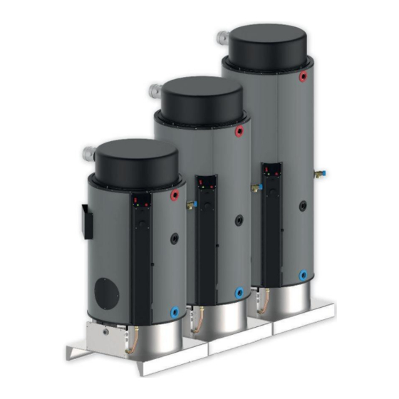
GAS STORAGE WATER HEATER
SEALED CHAMBER AND FORCED DRAFT
(type C)
.
SX160
SX220
SX300
SX400
SX600
SX800
ENG - Manual installation, use and
maintenance.
Original instructions.
Read and follow these instructions before installing the unit.
Always keep on hand this manual during the maintenance phase.
This manual is also available in electronic format and downloadable from the website.
www.atimariani.it
feb-21
ATI DI MARIANI SRL - Via E. Mattei, 461 - Industrial Area No. 4 Torre del Moro - 47522 Cesena (FC) - Italy
Tel .: +39 0547 609711 - Fax: +39 0547 609724 - Web: www.atimariani.it - Email: info@atimariani.it
IVA IT 00281090407 - REA 143693
ed 02-2021
Advertisement
Table of Contents

Related Manuals for ATI Technologies SX160

Summary of Contents for ATI Technologies SX160
- Page 1 1936 GAS STORAGE WATER HEATER SEALED CHAMBER AND FORCED DRAFT (type C) SX160 SX220 SX300 SX400 SX600 SX800 ENG - Manual installation, use and maintenance. Original instructions. Read and follow these instructions before installing the unit. Always keep on hand this manual during the maintenance phase.
-
Page 2: Table Of Contents
UK - Manual installation, use and maintenance. SUMMARY GENERAL WARNINGS ................................. 3 TRANSPORTATION, STORAGE AND RECYCLING ......................... 4 CORRECT DISPOSAL OF THIS PRODUCT ............................4 CONTENT, WEIGHT AND DIMENSIONS OF PACKAGE ......................... 5 CATEGORIES OF APPLIANCE ............................... 5 TECHNICAL DATA ..................................6 DESTINATION COUNTRIES AND GAS CATEGORIES ........................ -
Page 3: General Warnings
UK - Manual installation, use and maintenance. 1. GENERAL WARNINGS THIS BOOKLET IS AN INTEGRAL PART OF THE APPLIANCE AND ESSENTIAL AND MUST BE KEPT WITH CARE IN THE VICINITY OF THE APPLIANCE ITSELF FOR FUTURE CONSULTATION. It CONTAINS IMPORTANT INFORMATION REGARDING SAFETY, INSTALLATION, OPERATION AND MAINTENANCE. THE APPLIANCE HAS BEEN BUILT FOR THE PRODUCTION OF HOT WATER: ANY OTHER TYPE OF USE IS TO BE DEEMED NOT SUITABLE AND DANGEROUS. -
Page 4: Transportation, Storage And Recycling
UK - Manual installation, use and maintenance. 2. TRANSPORTATION, STORAGE AND RECYCLING The appliance must be transported and stored dry and protected from frost. The appliance must be stored, transported and used at a temperature between +10 and +40 ° C and at a humidity between 40% and 80%. -
Page 5: Content, Weight And Dimensions Of Package
UK - Manual installation, use and maintenance. 4. CONTENT, WEIGHT AND DIMENSIONS OF PACKAGE The appliance is delivered packaged in a wooden box with appropriate protection. See table below for size. SX160 SX220 SX300 SX400 SX600 SX800 Width Depth Height... -
Page 6: Technical Data
UK - Manual installation, use and maintenance. 6. TECHNICAL DATA SX160 SX220 SX300 SX400 SX600 SX800 Classe efficienza sanitaria - efficiency class Profilo di carico - load profile Capacità nominale serbatoio - tank nominal capacity Efficienza – efficiency Portata termica nominale Q - nominal calorific flow rate QN 13.5... -
Page 7: Dimensions And Equipment
UK - Manual installation, use and maintenance. 8. DIMENSIONS AND EQUIPMENT SX160 SX220 SX300 SX400 SX600 SX800 A HEIGHT APPARATUS 2035 1563 1913 2263 1928 2278 B IN OUT SMOKE 1915 1446 1796 2146 1821 2171 C OUTPUT HOT G 1-1 / 4 "... -
Page 8: Description Functional And Construction
UK - Manual installation, use and maintenance. 9. DESCRIPTION FUNCTIONAL AND CONSTRUCTION The function of this device is to generate hot water through the heat exchange between the combustion products of the burner and the water present in the storage tank. The combustion takes place in a completely sealed with respect to the device that contains, by withdrawing the air required for combustion from the outside and discharging the products of combustion itself always outside. -
Page 9: Components Of The Appliance
UK - Manual installation, use and maintenance. 10. COMPONENTS OF THE APPLIANCE A. THERMOMETER THERMOSTAT Measure the temperature inside the tank. Used to adjust the internal temperature of the tank. B. RED LIGHT BLOCK G. AIR PRESSURE Report device lock, to unlock, hold down the button for 3 It is used to verify and monitor the correct operation of the seconds. -
Page 10: Local Regulations, And Installation Of Safety
UK - Manual installation, use and maintenance. 11. LOCAL REGULATIONS, AND INSTALLATION OF SAFETY LOCAL REGULATIONS In the installation the local regulations must be observed regarding: Fire fighters Gas Company power Company Office hygiene and health SAFETY RULES Do not perform any cleaning or maintenance work without turning off the water heater and interrupting power supply. ... -
Page 11: Installation
UK - Manual installation, use and maintenance. 12. INSTALLATION OPERATION CARRIED OUT BY A QUALIFIED Warning! The installation of the residential ventilation system must be performed only by qualified personnel in order to avoid damage or injury. Before installing the appliance, ensure that the nominal supply voltage is 220 / 240V - 50 / 60Hz. ... -
Page 12: Installation Cover Smoke Extraction
UK - Manual installation, use and maintenance. 14. INSTALLATION COVER SMOKE EXTRACTION The fume hood box, delivered separately, contains: A. cap in black painted aluminum B. Fan Group C. coaxial fitting Ø 60/100 with Flue gas bag fixing screws Connect the two grommets to the pressure taps. IMPORTANT : pink eraser: 1 socket (metal) neutral eraser: socket 2 (plastic) -
Page 13: Exhaust Fumes
UK - Manual installation, use and maintenance. 15. EXHAUST FUMES The installation of the exhaust terminals must comply with the regulations in force. In any case, any provisions foreseen by municipal, provincial or sectorial regulations must be respected. The flue gases of several boilers must not be conveyed inside the same flue gas exhaust pipe: each boiler must have its own independent exhaust pipe. - Page 14 UK - Manual installation, use and maintenance. To increase the drain length it is necessary to purchase the appropriate extensions proposed in the following table. The maximum supported extension is shown in the previous table. Each curve is equivalent to 1 meter of the total length. The choice of the type of drain must take into account local and national regulations.
- Page 15 1 m H + 1 m H + 1 m V 1 m V 2 m V 3 m V 4 m V Ø82 Ø82 Ø82 Ø82 Ø84 SX160 Ø84 Ø86 Ø40 Ø42 Ø44 Ø44 Ø44 Ø82 Ø84 Ø84 Ø90 Ø92...
-
Page 16: Hydraulic Connections
16. HYDRAULIC CONNECTIONS The connection to the water mains must be made with a G 3/4 "pipe for the SX160 model or G 1-1 / 4" for the rest of the models. The cold water inlet is identified by the blue ring, while the hot water outlet is identified by the red ring). -
Page 17: Trunk Gas
UK - Manual installation, use and maintenance. 17. TRUNK GAS Connect the gas supply line of the thread, present on the appliance, by means of a removable rigid connector: the pipe must exit through the slot of the appliance. The attack gas connection is G 1/2 ": it is recommended to mount along the pipe, in the vicinity of the generator and in an easily accessible location, a faucet interception manual gas. -
Page 18: Ignition And Temperature Control
UK - Manual installation, use and maintenance. 19. IGNITION AND TEMPERATURE CONTROL POWER AND CONTROL THERMOSTAT A. switch B. control thermostat C. thermostat safety limiter (manual reset) D. thermometer E. bright green light operation F. reset button 44° 50° 58° 62°... -
Page 19: Gas Change
UK - Manual installation, use and maintenance. 20. GAS CHANGE To change the gas, use only the special gas conversion kit prepared by the manufacturer, indicated in the table below, carefully following the following instructions contained in the kit. Device SX160 SX220 SX300 SX400 SX600... - Page 20 UK - Manual installation, use and maintenance. Models SX220 SX300 SX400 SX600 SX800 Switch off the appliance, close the gas interception valve and disconnect the power supply Remove the burner door (A) and the insulating material (B) Unscrew the gas pipe (E) TRANSFORMATION OF GAS SUPPLY TRANSFORMATION OF GAS SUPPLY TO PROPANE G31...
-
Page 21: Wiring
UK - Manual installation, use and maintenance. 21. WIRING THE: Line N: Neutral THE: Switch SB: red lock lamp RESET: reset button T: Control thermostat SA: Power indicator VG1: valve GAS TS: Water Safety thermostat ACC: Ignition electrode ION: Detection electrode V: Frequency Ventilator AP: Air pressure F1: Fuse 4 A fast type 250 V... -
Page 22: Periodic Maintenance
22. PERIODIC MAINTENANCE To ensure the safety of the appliance and extend its life, it is mandatory to have it checked at least once a year by an authorized service center, which will carry out the following operations: replacement of the magnesium anode ... -
Page 23: Diagnostic Tool
25. DIAGNOSTIC TOOL The red light in the reset button is able to indicate the type of error. The light switches on intermittently according to the type of burner ignition impediment, with a series of pulses and a pause of 2s between one series and the next. ERROR DIAGNOSTIC TABLE Type of signal Mistake... - Page 24 ATI DI MARIANI SRL Via E. Mattei, 461 Zona Ind. No. 4 Torre del Moro 47522 Cesena (FC) - ITALY Tel. +39-0547 609711 Fax 0547 609724 www.atimariani.it info@atimariani.it 210-0203_Libretto_SX-ind_ATI_2021-02_GB.docx Ed 2021-02...
Need help?
Do you have a question about the SX160 and is the answer not in the manual?
Questions and answers