
Summary of Contents for ZIEHL-ABEGG NETcon A-G-102ANE
- Page 1 english NETcon A-G-102ANE 380087 Digital Operating and Display Device Operating Instructions Software version: Valid from software version 1.01 L-BAL-E156-GB 2105 Index 004 Part.-No.
-
Page 2: Table Of Contents
Operating Instructions NETcon A-G-102ANE Content General notes .......... - Page 3 Operating Instructions NETcon A-G-102ANE Operating the NETcon ........
-
Page 4: General Notes
We do not accept any liability for possible errors or omissions in the information con- tained in data, illustrations or drawings provided. ZIEHL-ABEGG SE is not liable for damage due to misuse, incorrect use, improper use or as a consequence of unauthorized repairs or modifications. -
Page 5: Safety Instructions
Operating Instructions NETcon A-G-102ANE Safety instructions 2 Safety instructions 2.1 Intended use The equipment is to be used solely for the purposes specified and confirmed in the order. Any other use above and beyond this is considered not for the intended purpose unless agreed otherwise by contract. -
Page 6: Explanations Of Symbols
Operating Instructions NETcon A-G-102ANE Safety instructions 2.2 Explanations of symbols Safety instructions are highlighted with warning triangles and are depicted according to the degree of hazard as follows. Attention! General hazardous area. Death or severe injury or significant property damage can... -
Page 7: Work On The Device
ZIEHL-ABEGG.These parts were specifically designed for the device. There is no guarantee that parts from non-original sources are designed and manufactured in correspondence with load and safety requirements. Parts and optional equipment not supplied by ZIEHL-ABEGG are not approved by ZIEHL-ABEGG for use. 2.8 Operator’s obligation of diligence •... -
Page 8: Employment Of External Personnel
Operating Instructions NETcon A-G-102ANE Product overview • All safety and warning notices attached to the device are never removed and remain legible. 2.9 Employment of external personnel Maintenance and service work are frequently carried out by external employees who often do not recognize the specific situations and the thus resulting dangers.These persons must be comprehensively informed about the hazards in their area of activity. -
Page 9: Mounting
Operating Instructions NETcon A-G-102ANE Mounting 4 Mounting 4.1 General notes Attention! The following points must be complied with during the mechanical installation to avoid causing a defect in the device due to assembly errors or environmental influences: • Before installation remove the device from the packing and check for any possible shipping damage! Start-up is not allowed in the case of transport damage! •... -
Page 10: Electrical Installation
Operating Instructions NETcon A-G-102ANE Electrical installation 5 Electrical installation 5.1 Safety precautions Danger due to electric current • Work on electric components may only be carried out by trained electricians or by persons instructed in electricity under the supervision of an electrician in accordance with electrical engineering regulations. -
Page 11: Voltage Supply
Operating Instructions NETcon A-G-102ANE Electrical installation 5.3 Voltage supply The supply voltage is connected to terminals "V+ " and "V- ". Here, it must strictly observed that the supply voltage lies within the allowable tolerance specifications. Supply voltage: 24 V DC +/- 10 % (400 mA) Option: Power supply for switch cabinet mounting Type STEP-PS/1AC/24DC/1.75... -
Page 12: Digital Input "D2" (Stop / Start)
Operating Instructions NETcon A-G-102ANE Electrical installation 5.4.2 Digital input "D2" (Stop / Start) Via the digital input "D2", all connected fans can be stopped or started (e.g. during revision work). For using this function, the digital input "D2" has to be activated first in the menu group "INTERN". -
Page 13: Rs-485 - Network Design And Interface Parameter
Operating Instructions NETcon A-G-102ANE Electrical installation 5.6.2 RS-485 - network design and interface parameter Please ensure the correct connection; i.e. "A (D+)" must always be connected to "A (D+)" of the next devices. The same applies to "B (D-)" . -
Page 14: Operating The Netcon
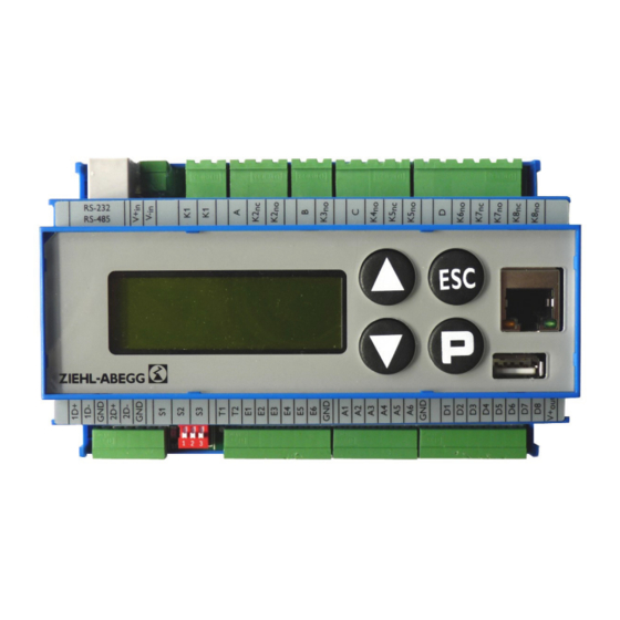
Operating Instructions NETcon A-G-102ANE Operating the NETcon Information If any matters are unclear, please contact our V-STE support department for control systems - ventilation technology. The information sheet “Network structure of MODBUS” R-TIL08_01 contains detailed information about “MODBUS”. 6 Operating the NETcon 6.1 Controls and LCD-display... -
Page 15: Menu Structure
Operating Instructions NETcon A-G-102ANE Operating the NETcon 6.2 Menu structure The fault-free state of a system is indicated by “System o.k.”. An error is only Ziehl-Abeg- shown on the display when it occurs. l-Abegg ECblue If no keys are pressed within 90 seconds, the NETcon returns automatically to System o.k. - Page 16 Operating Instructions NETcon A-G-102ANE Operating the NETcon FAN INFO xx FAN INFO xx FAN SET xx ON FAN 17 02 849rpm Speed 1200rpm max 0rpm Speed MOTOR 850rpm Se- Speed 850rpm Se- BLOCKED SetIntern2 0rpmmin SetIntern2 04.05.2011 1- NO ER-...
- Page 17 Operating Instructions NETcon A-G-102ANE Operating the NETcon ▲ ▼ ▲ ▼ BROADCAST E- FAN ADDRES- INTERN EDIT EDIT DDRESS EDIT ENABLE D2 850rpm Se- 05 FANs con- STOP SetIntern2 connected ENABLE new 07 new (Au- (Autoaddr) ▲ ▼ BROADCAST E-...
-
Page 18: Operation And Parameterising
Operating Instructions NETcon A-G-102ANE Operating the NETcon 6.2.2 Operation and parameterising The selection of the meun group takes place with the arrow keys to the right with [▲], to the left with [▼]. The parameter of the menu group are displayed with [P]. With the arrow keys you can move up and down inside the menu group. - Page 19 Operating Instructions NETcon A-G-102ANE Operating the NETcon Thereupon appear FAN SET 03 ON the first parameters 1200rpm max "max Speed", "min Speed Speed" (only infor- 0rpmmin Speed mation) with the cur- rent values (FAN 3). The next parameter is shown, when [▲] is pressed again.
-
Page 20: Start-Up
Operating Instructions NETcon A-G-102ANE Start-up 7 Start-up 7.1 Prerequisites for commissioning Attention! 1. You must mount and connect the device in accordance with the operating instructions. 2. Double check that all connections are correct. 3. The supply voltage must match the information on the rating plate. - Page 21 Operating Instructions NETcon A-G-102ANE Start-up FAN ADDRESS E- EDIT Upon completion of the automatic addressing are the addressed fans 00 FANs con- shown in the display [Display line: 07 new (AutoAddr)]. The installation connected 07 new (Au- process will stored with 2x [P] and completed with [ESC].
-
Page 22: Connection Options
Operating Instructions NETcon A-G-102ANE Start-up 7.3 Connection options It is essential to connect the terminal "ID" of the first fan with the terminal "GND", that the automatic addressing can be performed. 7.3.1 Conventional connection (1D+) (1D-) (2D+) (2D-) ECblue MODBUS ECblue MODBUS 3...63... -
Page 23: Programming
Operating Instructions NETcon A-G-102ANE Programming 8 Programming 8.1 Menu group FAN INFO FAN INFO see connected ECblue 01 - 05 FAN INFO Actual value display for speed and various set-values. The menu group “FAN INFO” is a real information menu. It shows speed, speed set value and number of the installed fans. -
Page 24: Menu Group Error
Operating Instructions NETcon A-G-102ANE Programming 8.2 Menu group ERROR ERROR Error History Fault and alarm display If a fault occurs, the alarm relay is triggered so that a klaxon can be initiated ( Alarm relay). In addition, the display of the NETcon changes automatically to the now flashing menu “Error”, where the affected fan, the type of fault and the date plus time of the occurrence is displayed. -
Page 25: Menu Group Pin
Operating Instructions NETcon A-G-102ANE Programming 8.3 Menu group PIN PIN EDIT PIN required XXXX Inserting the PIN is intended to prevent accidental alterations to the NETcon and its operating characteristics. The PIN is deleted automatically if no key is pressed within 15 minutes, also after a voltage reset or after the insertion of an incorrect PIN. - Page 26 Operating Instructions NETcon A-G-102ANE Programming FAN SET 01 ON 1300rpm max Speed 0rpmmin Speed Min. / Max. Speed (only information menu) Chapter "FAN INFO" FAN SET 01 EDIT ON in Fan ON new ctrl-enable Ein / Aus Fan ON or OFF...
-
Page 27: Menu Group Broadcast
Operating Instructions NETcon A-G-102ANE Programming 8.5 Menu group BROADCAST BROADCAST common settings to ALL FANs BROADCAST The settings applies for all connected and addressed fans BROADCAST EDIT *** ctrl-enable Fans ON or OFF ON ctrl-enable - all fans "ON" OFF ctrl-enable - all fans "OFF"... -
Page 28: Menu Group Fan Address
Operating Instructions NETcon A-G-102ANE Programming 8.6 Menu group FAN ADDRESS FAN ADDRESS Set/Get No. of ECblue FAN ADDRESS Addressing of the fans FAN ADDRESS EDIT NOT Autoaddressing Selection automatically / manually addressing "NOT Autoaddressing" - manual addressing "DO Autoaddressing" - automatic addressing... - Page 29 Operating Instructions NETcon A-G-102ANE Programming Alarm relay on / off INTERN EDIT For revision reasons, the alarm relay can get disabled. ENABLE Alarm The deactivation is shown in the display through a flashing notice. Relais ENABLE new After a power reset of the NETcon, the alarm relay is always activated.
-
Page 30: Enclosure
Operating Instructions NETcon A-G-102ANE Enclosure 9 Enclosure 9.1 Technical data 4-line LCD display and 4 buttons for installation, parameterization and monitoring of fans Voltage supply 24 V DC +/- 10 % (400 mA) • 1x RS-485 ("1A (1D+)", "1B (1D-)", "GND") Interfaces •... -
Page 31: Connection Diagram
Operating Instructions NETcon A-G-102ANE Enclosure 9.2 Connection diagram Spannungsversorgung Power supply 24 V DC A-G-102ANE RJ11 RS-232 RS-485 Kontaktbelastung Contact rating RJ45 max. AC 250 V 2 A A6 GND D8 V+ (1D+) (1D-) (2D+) (2D-) Digitale Eingänge für potentialfreie Kontakte... -
Page 32: Manufacturer Reference
Operating Instructions NETcon A-G-102ANE Enclosure 9.4 Manufacturer reference Our products are manufactured in accordance with the relevant international regulations. If you have any questions concerning the use of our products or plan special uses, please contact: ZIEHL-ABEGG SE Heinz-Ziehl-Straße 74653 Künzelsau phone: +49 (0) 7940 16-0 info@ziehl-abegg.de...
Need help?
Do you have a question about the NETcon A-G-102ANE and is the answer not in the manual?
Questions and answers